
Device for supporting systems

a technology of supporting system and device, which is applied in the direction of lighting support device, washstand, scaffold accessories, etc., can solve the problem that the route of electrical cables to be laid is hardly possible, and achieve the effect of reducing the number of components, reducing assembly costs, and reducing aircraft weigh

Active Publication Date: 2013-09-17
AIRBUS OPERATIONS GMBH
View PDF44 Cites 8 Cited by
  • Summary
  • Abstract
  • Description
  • Claims
  • Application Information

AI Technical Summary

Benefits of technology

Enables flexible and optimal routing of cables or pipes during assembly, improving safety and reducing production costs by allowing for adjustable configurations without compromising structural stability.

Problems solved by technology

In the device of prior art it turned out to be disadvantageous that a change in the route of the electrical cable to be laid is hardly possible during the equipment assembly because the A-bracket is firmly riveted to the structure.

Method used


Image

  • Device for supporting systems
  • Device for supporting systems
  • Device for supporting systems

Examples


second embodiment

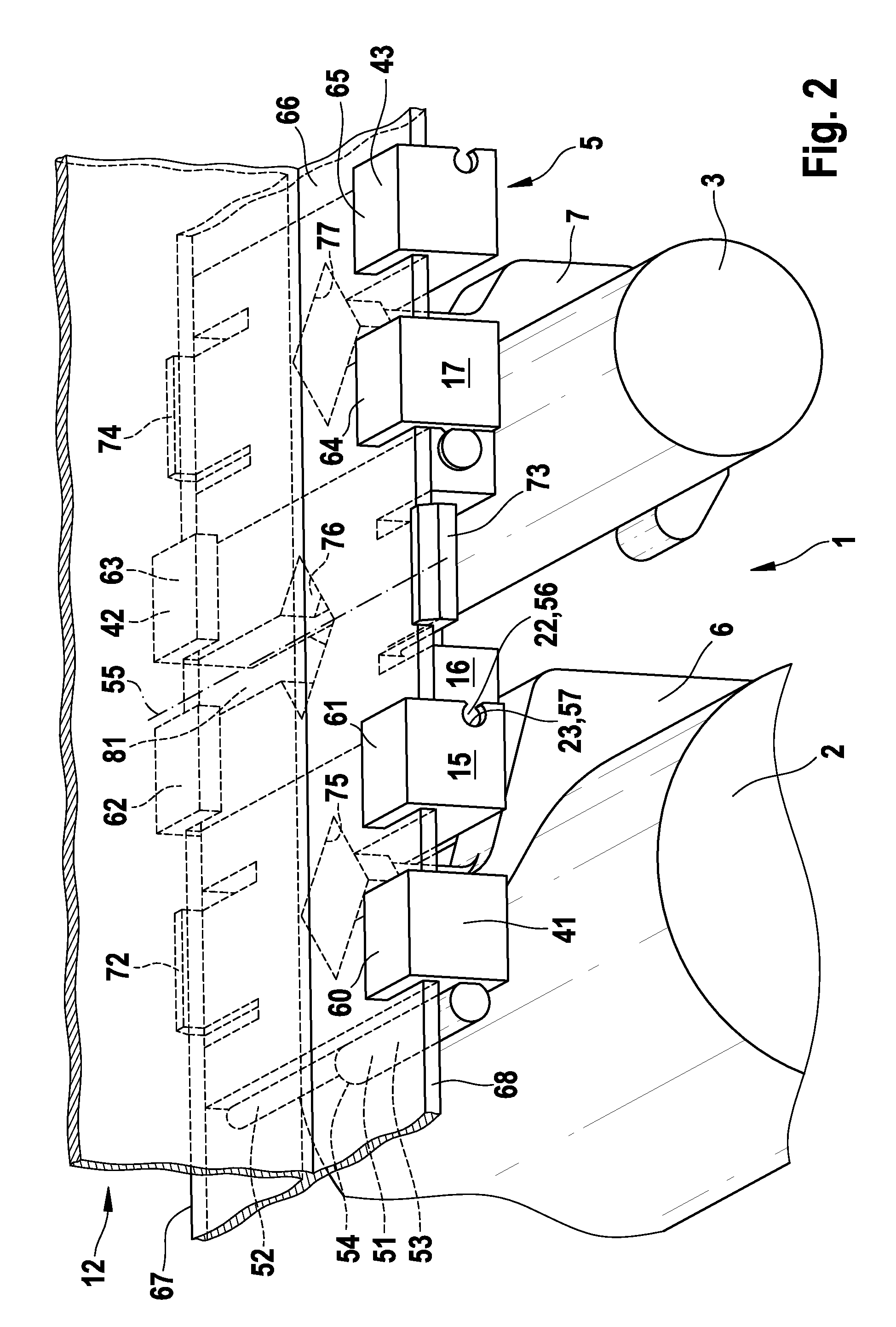
[0088]FIG. 2 shows, in a perspective partial view, a section of an aircraft or space craft according to this invention.

[0089]For greater clarity FIG. 2 shows, in a section from FIG. 1, only the basic chain link brackets 15, 16, 17.

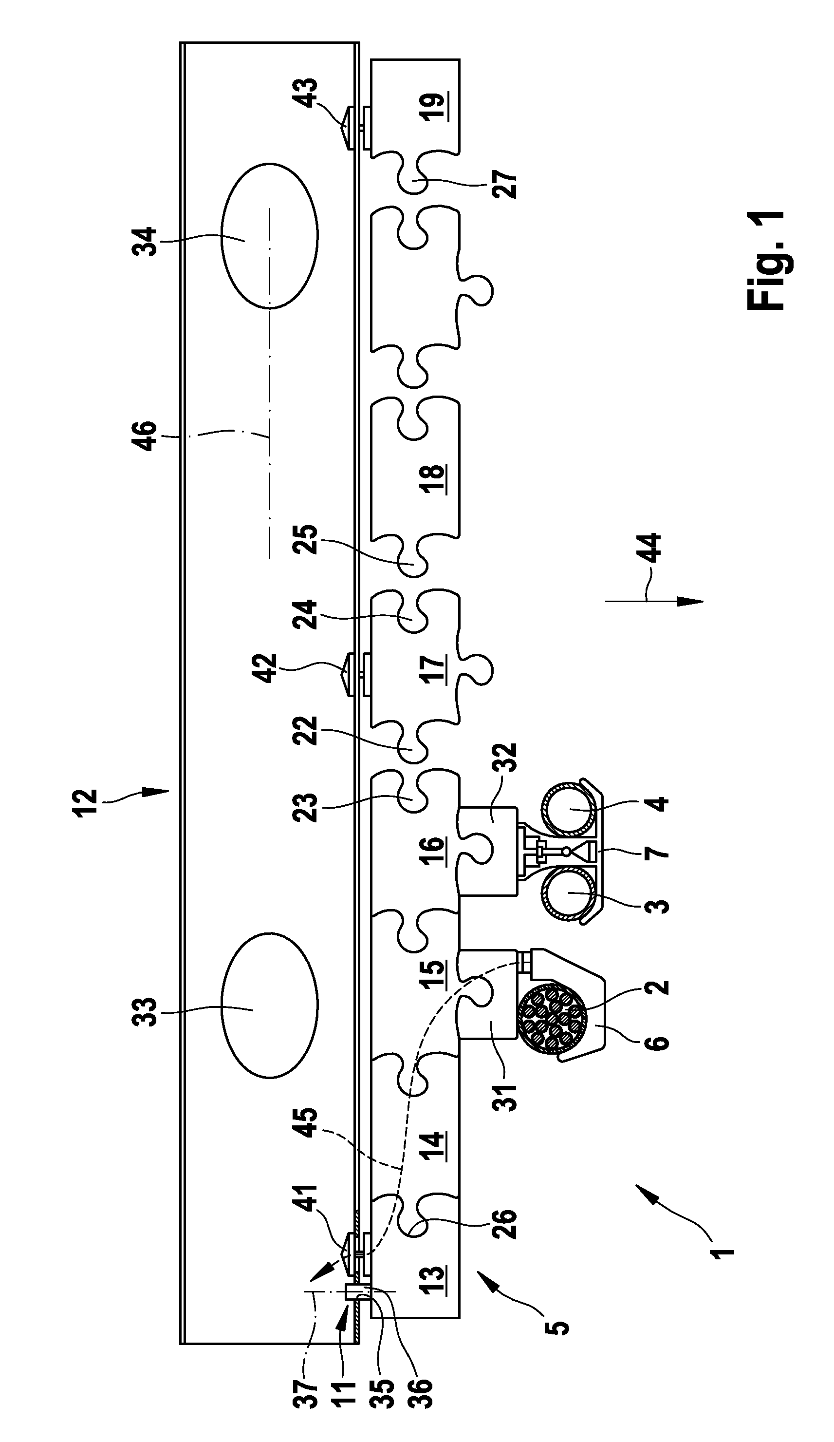
[0090]In the following only differences relative to the exemplary embodiment according to FIG. 1 will be discussed.

[0091]In the embodiment according to FIG. 2 the engaging element 22 is designed as a pin 51, 56 and the receiving element 23 as a bushing 57, pin 51, 56 being rotatably mounted in bushing 57. The pin (explained by the example of pin 51 for the sake of clarity) is composed of two cylindrical sections 52, 53, wherein cylindrical section 52 forms, with cylindrical section 53, a shoulder 54 which bears against a corresponding shoulder (not shown) of the bushing 57 of the basic chain link bracket 16 interlinked with basic chain link bracket 15, when these brackets are interlinked, and therefore positions the basic chain link brackets 15, 16 in a de...


PUM


Abstract

The present invention relates to a device for supporting systems, for example an electric cable or a fluid-carrying pipe, on a structure of an aircraft or space craft, and to an aircraft or space craft with such a device. The device has a basic bracket arrangement which can be fastened to at least one predetermined fastening section of the structure, and also has at least one system bracket for supporting the systems. The at least one system bracket can be fastened to the basic bracket arrangement locationally variable with respect to the fastening section. The advantage of the invention consists in the fact that a route of a system can be flexibly varied even during the equipment assembly, i.e. the structure is no longer modifiable or is only modifiable at considerable expense.

Description

FIELD OF INVENTION[0001]The present invention relates to a device for supporting systems, for example an electrical cable or a fluid-carrying pipe, on a structure of an aircraft or space craft, and to an aircraft or space craft with such a device.[0002]Although applicable to any systems and aircraft or space craft, this invention and the problem on which it is based are explained with reference to an electrical cable in a passenger aircraft. The contents of U.S. Provisional Application No. 60 / 941,399 is herein included by cross-reference.BACKGROUND OF THE INVENTION[0003]In a modern passenger aircraft a multiplicity of electrical components has to be connected to each other by means of electrical cables. If a distance between two electrical components to be connected exceeds a certain value, it is necessary, in particular for safety reasons and for reasons of order, to support the electrical cable provided for connecting the electrical components along its route between the electrica...

Claims


Application Information

Patent Timeline
Patent Type & Authority Patents(United States)
IPC IPC(8): A47B96/00
CPCH02G3/32F16L3/24F16B3/00
Inventor LUNITZ, BARBARAGUTHKE, HANS PETERJUENEMANN, MARCUS
Owner AIRBUS OPERATIONS GMBH
Learn More