
Optical rotation plate and liquid crystal display device using the same

a technology of optical rotation and liquid crystal display, which is applied in the direction of liquid crystal compositions, instruments, chemistry apparatus and processes, etc., can solve the problems of difficult control of the twist angle, image observed in a state with the polarizing glasses on darkened, and difficult to observe bright images. , to achieve the effect of enabling observation of bright images

Inactive Publication Date: 2013-09-10
DAI NIPPON PRINTING CO LTD
View PDF20 Cites 1 Cited by
  • Summary
  • Abstract
  • Description
  • Claims
  • Application Information

AI Technical Summary

Benefits of technology

The present invention provides an optical rotation plate that can achieve a desired rotation angle while minimizing the variation in the rotation angle of the polarization specializing axis of linear polarization. Additionally, the invention allows for the observation of a bright image even when wearing polarization glasses.

Problems solved by technology

However, on the other hand, since the linear polarization is converted into the circular polarization so that the light supplied to the display is dispersed in the all directions, a problem is involved in that the image observed in a state with the polarizing glasses put on is darkened.
However, since the depolarization plate is extremely expensive so that it is not suitable for the liquid crystal display device to which cost reduction is required due to drastic market expansion, and furthermore, since the light supplied to the display is dispersed in the all directions, a problem is involved in that the image observed in a state with the polarizing glasses put on is darkened.
Furthermore, in general, it is difficult to control the twist angle of the liquid crystal material without variation so that in the case of forming such a rotating plate in a large area, variation is generated in the rotation angle according to the variation of the twist angle so that a problem arises in that a homogeneous image can hardly be observed in a state with the polarizing glasses put on.

Method used


Image

  • Optical rotation plate and liquid crystal display device using the same
  • Optical rotation plate and liquid crystal display device using the same
  • Optical rotation plate and liquid crystal display device using the same

Examples


first embodiment

I. First Embodiment

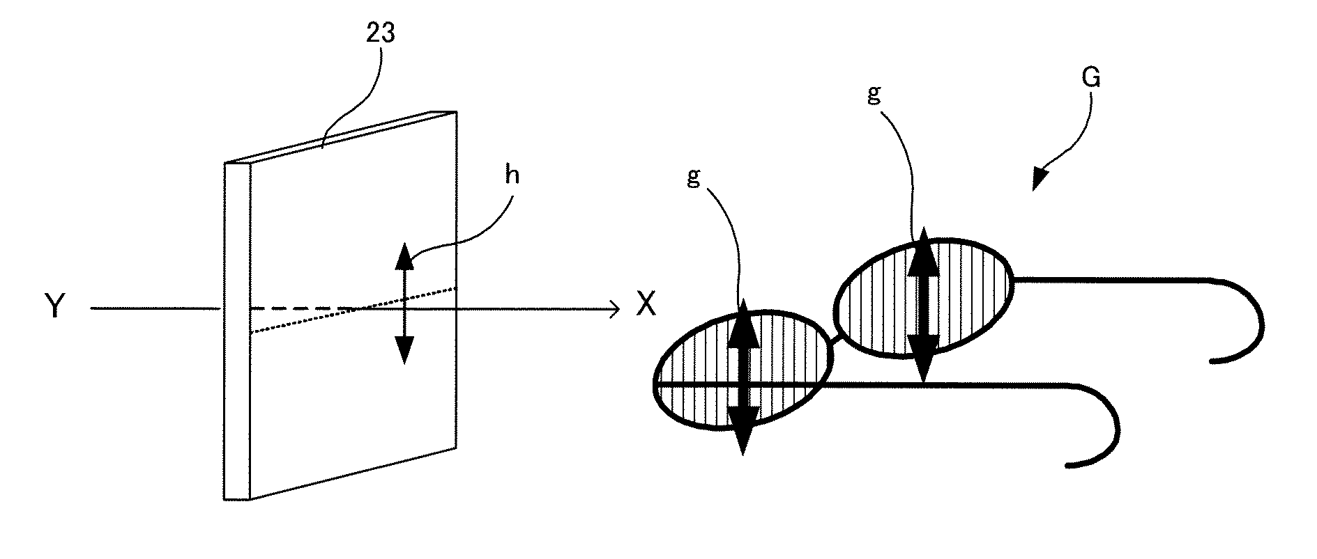
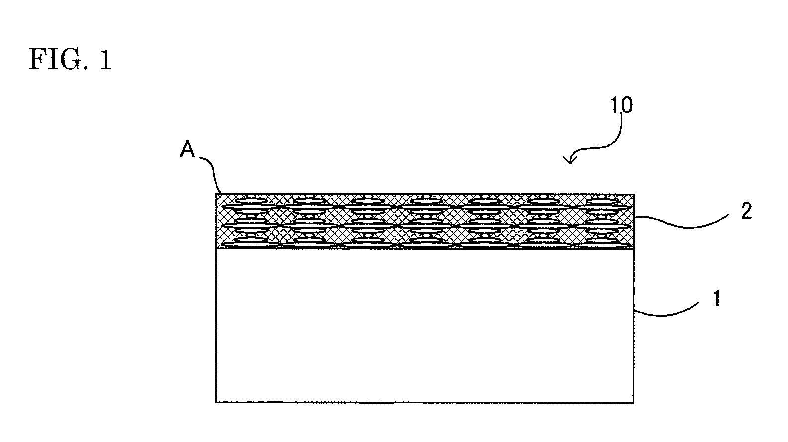
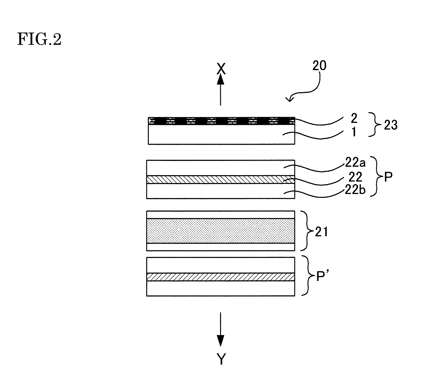
[0105]The liquid crystal display device of the first embodiment comprises a liquid crystal cell, a polarizer disposed on the display side of the above-mentioned liquid crystal cell, and an optical rotation plate disposed on the display side of the polarizer and having a function of rotating the polarization axis of linear polarization transmitted the above-mentioned polarizer, wherein the above-mentioned optical rotation plate further comprises a transparent substrate, and an optical rotation layer formed on the above-mentioned transparent substrate and containing a rod-shaped compound for forming a cholesteric structure, with the above-mentioned cholesteric structure having a twist angle of 90 degrees or larger and a pitch in a range of 450 nm to 4,000 nm.

[0106]Such a liquid crystal display device of this embodiment will be described with reference to drawings. FIG. 2 is a schematic cross-sectional view showing an example of the liquid crystal display device of t...

second embodiment

II. Second Embodiment

[0129]Then, the second embodiment of the liquid crystal display device of the present invention will be described.

[0130]The liquid crystal display device of the second embodiment comprises a liquid crystal cell, a polarizer disposed on the display side of the above-mentioned liquid crystal cell, and an optical conversion layer disposed on the display side with respect to the above-mentioned polarizer and having a function of converting linear polarization transmitted the above-mentioned polarizer to elliptical polarization.

[0131]Such a liquid crystal display device of this embodiment will be described with reference to the drawings. FIG. 11 is a schematic cross-sectional view showing an example of the liquid crystal display device of this embodiment. As illustrated in FIG. 11, the liquid crystal display device 20 of this embodiment comprises a liquid crystal cell 21, a polarizer 22 disposed on the display side of the above-mentioned liquid crystal cell, and an o...

example 1

[0185]A cyclohexanone solution (solid component 40 parts by weight) was prepared by dissolving 95.3 parts by weight of a liquid crystalline monomer molecule having polymerizable acrylate at both ends and a spacer between mesogen at the center part and the above-mentioned acrylate (Paliocolor (registered trademark) LC1057 (manufactured by BASF Corp.)), 4.7 parts by weight of a chiral agent molecule having polymerizable acrylate at the end of both sides (Paliocolor (registered trademark) LC756 (manufactured by BASF Corp.)), and 2.5 parts by weight of a photo polymerization initiating agent with respect to the above-mentioned liquid crystalline monomer.

[0186]By applying the above-mentioned cyclohexanone solution onto the glass substrate with an alignment film with a spin coater, evaporating the cyclohexanone in the above-mentioned cyclohexanone solution at 80° C., and maintaining the temperature at 100° C. for 2 minutes, the liquid crystalline monomer molecule was aligned. Then, by dir...


PUM

PropertyMeasurementUnit
selective reflection wavelengthaaaaaaaaaa
twist angleaaaaaaaaaa
wavelengthaaaaaaaaaa

Abstract

A main object of the present invention is to provide a rotating plate hardly generating variation in the rotation angle of the liner polarization so as to easily realize a desired rotation angle, and a liquid crystal display device enabling observation of a bright image by use thereof even in a state with a polarizing glasses put on. To attain the object, the present invention provides an optical rotation plate comprising a transparent substrate, and an optical rotation layer formed on the transparent substrate and containing a rod-shaped compound for forming a cholesteric structure and having a function of rotating transmitted liner polarization, wherein the cholesteric structure has a 90 degrees or larger twist angle and a pitch in a range of 450 nm to 4,000 nm.

Description

FIELD OF THE INVENTION[0001]The present invention relates to an optical rotation plate having a function of rotating linear polarization, and a liquid crystal display device using the optical polarizing plate enabling observation without darkening the display even in a state of wearing polarizing glasses.DESCRIPTION OF THE RELATED ART[0002]In a current liquid crystal display device, the polarization state of a display light ejected from a display screen is linear polarization. For example, when the liquid crystal display device is viewed from the front side, in the case of the TN mode, the polarization transmission axis is set so as to be oriented in the oblique direction of the screen in most cases. On the other hand, in the case of the VA mode or the IPS mode, it is oriented in the vertical direction in many cases. However, among those used for the advertisement for the exterior or interior uses, some have only the circuit change so as to be installed longitudinally in the vertica...

Claims


Application Information

Patent Timeline
Patent Type & Authority Patents(United States)
IPC IPC(8): G02F1/1347
CPCG02F1/133636G02B5/3016G02B27/26G02B27/286G02F2001/133633G02B30/25G02F1/133633
Inventor HAMADA, SATORUKASHIMA, KEIJIKURODA, TAKASHIYUMOTO, HIROFUMI
Owner DAI NIPPON PRINTING CO LTD
Learn More