Liquid crystal display device
a technology of liquid crystal display and light source module, which is applied in the direction of lighting support devices, instruments, lighting and heating apparatus, etc., can solve the problems of high application voltage still required for devices, device operation and module drive techniques that have not reached the technical level of products, and the configuration of a light source module as an illumination device has not yet been sufficiently optimized, etc., to achieve simple operation response and voltage control
- Summary
- Abstract
- Description
- Claims
- Application Information
AI Technical Summary
Benefits of technology
Problems solved by technology
Method used
Image
Examples
first embodiment
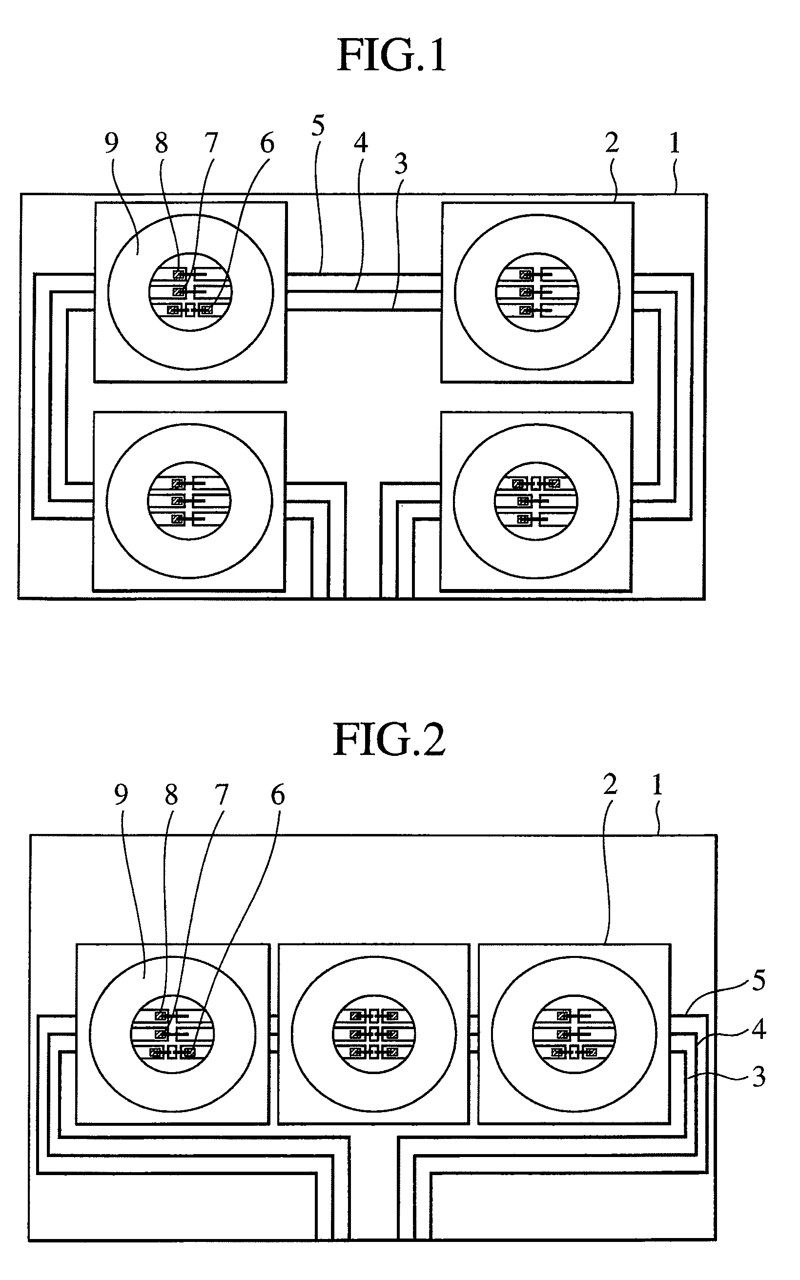
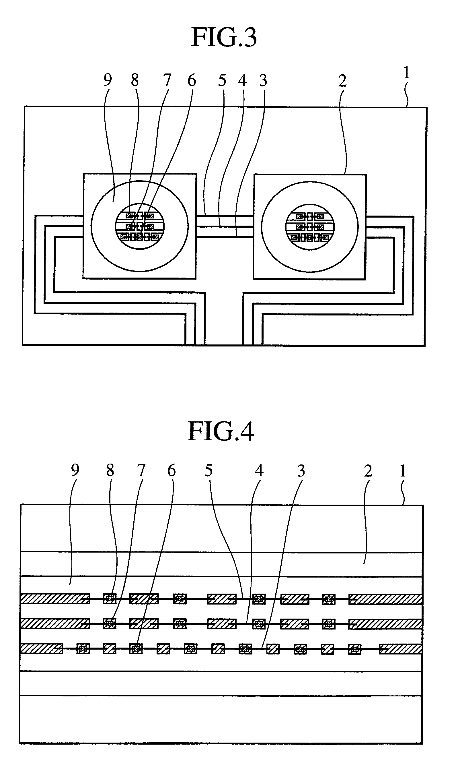
[0071]A first embodiment of the present invention will be explained below with reference to FIGS. 1 to 12.
[0072]With the first embodiment, a plurality of R-, G-, and B-LED devices are mounted on a wiring substrate, and a constant power voltage is applied to the R-, G-, and B-LED device wiring lines.
[0073]With arrangements of FIGS. 1 to 4, a reflector 2 is provided on a metal substrate with an insulating layer or a ceramic substrate 1. R-LED devices 6 (having a peak in a wavelength region from 610 nm to 640 nm), G-LED devices 7 (having a peak in a wavelength region from 510 nm to 540 nm), and B-LED devices 8 (having a peak in a wavelength region from 445 nm to 475 nm) are mounted in a R-LED device wiring line 3, a G-LED device wiring line 4, and a B-LED device wiring line 5, respectively, and sealed in a package by use of transparent resin 9. In this example, six R-LED devices, four G-LED devices, and four B-LED devices are respectively mounted in the R, G, and B wiring lines.
[0074]T...
second embodiment
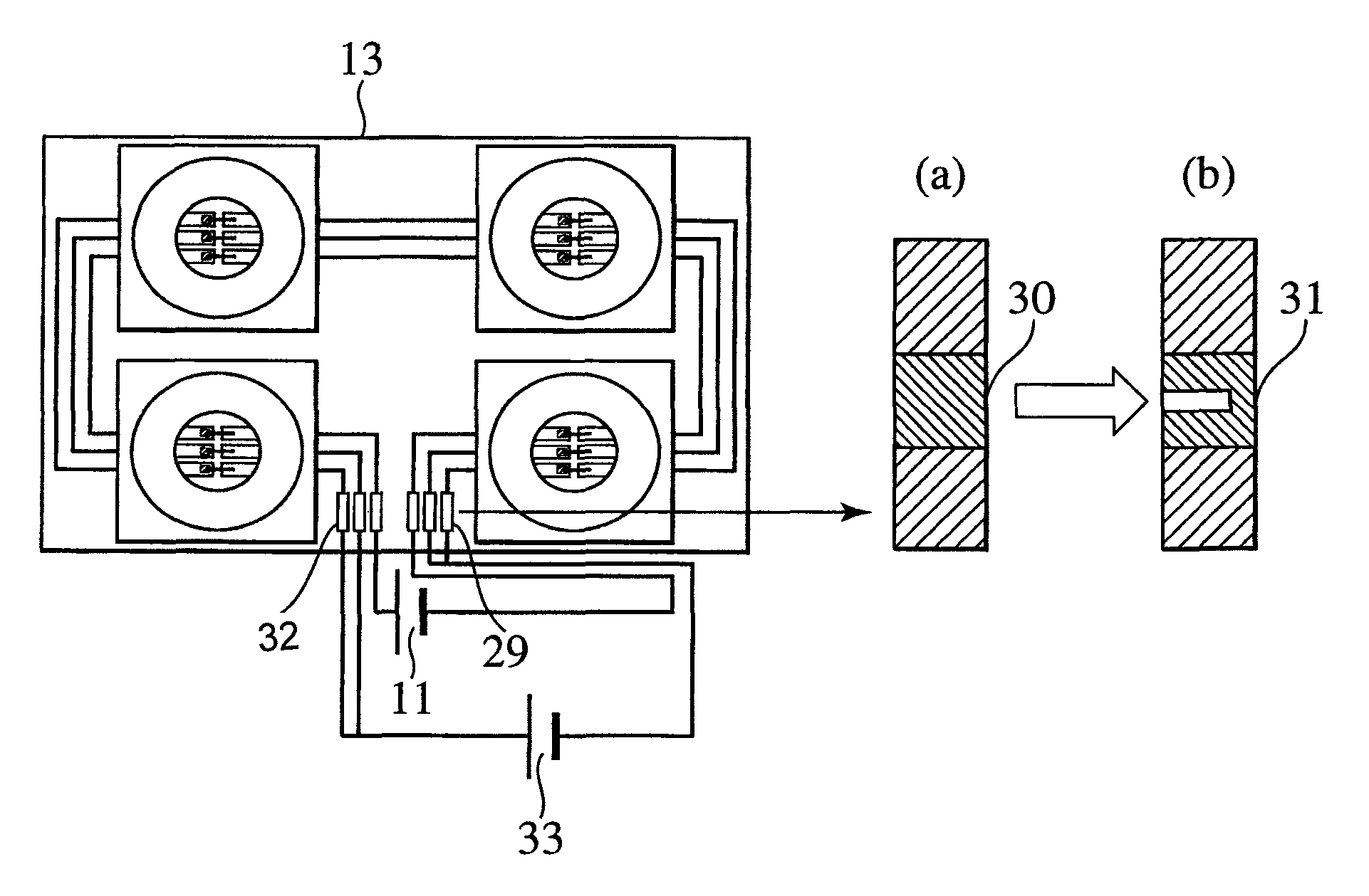
[0089]A second embodiment of the present invention will be explained below with reference to FIGS. 13 to 15.
[0090]Although the present embodiment configures a wiring substrate unit like in the first embodiment, the present embodiment is characterized in that a wiring resistance is provided in advance in each of the R-, G-, and B-LED device wiring lines. In the wiring substrate unit, a difference occurs in current-voltage characteristics of R-, G-, and B-LED devices resulting in characteristic variation and, therefore, it is necessary that LED devices can be driven by a constant power voltage. In order to enable operation as a backlight of a liquid crystal display device on a required power voltage 12V, a resistance required for each of the R-, G-, and B-LED device wiring lines is monitored beforehand. It is possible to determine a difference between the monitored resistance and the actually measured resistance by comparing these values in the inspection process. During inspection, a...
third embodiment
[0095]A third embodiment of the present invention will be explained below with reference to FIGS. 16 to 28.
[0096]Similar to the second embodiment, the present embodiment configures a wiring substrate unit and is characterized in that a zener diode, as represented by zener diode 32 in FIGS. 16, 17, 20 and 21 and circuit with zener diode 34 in FIGS. 24 and 27, for example, is provided in each of the R-, G-, and B-LED device wiring lines. The present embodiment is provided with a function to drive the LED devices on a 12V or 24V drive voltage while adjusting the resistance of resistance wiring through function trimming and performing temperature compensation of the operating voltage by use of a zener diode, simultaneously with LED device lighting inspection for each line.
[0097]First of all, an example for applying this function to the R-LED device wiring line is shown. FIG. 16 is a diagram showing a case where a zener diode is provided in the R-LED device wiring line. Four R-LED device...
PUM
| Property | Measurement | Unit |
|---|---|---|
| power voltage | aaaaa | aaaaa |
| power voltage | aaaaa | aaaaa |
| single power voltage | aaaaa | aaaaa |
Abstract
Description
Claims
Application Information
 - R&D
- Intellectual Property
- Life Sciences
- Materials
- Tech Scout
- Unparalleled Data Quality
- Higher Quality Content
- 60% Fewer Hallucinations
Browse by: Latest US Patents, China's latest patents, Technical Efficacy Thesaurus, Application Domain, Technology Topic, Popular Technical Reports.
© 2025 PatSnap. All rights reserved.Legal|Privacy policy|Modern Slavery Act Transparency Statement|Sitemap|About US| Contact US: help@patsnap.com


