
Method for separating blind signal and apparatus for performing the same

a blind signal and separation method technology, applied in the field of signal processing technique, can solve the problems of inability to apply a method, the performance of the method may be degraded, and the inability to apply to a case in which there are three or more signal sources, so as to improve the separation performance

Inactive Publication Date: 2013-08-27
ELECTRONICS & TELECOMM RES INST +1
View PDF11 Cites 5 Cited by
  • Summary
  • Abstract
  • Description
  • Claims
  • Application Information

AI Technical Summary

Benefits of technology

[0029]An aspect of the present invention provides a method for separating a blind signal capable of solving permutation of a separation filter without advance information regarding a sensor array and thus improving the separation performance.
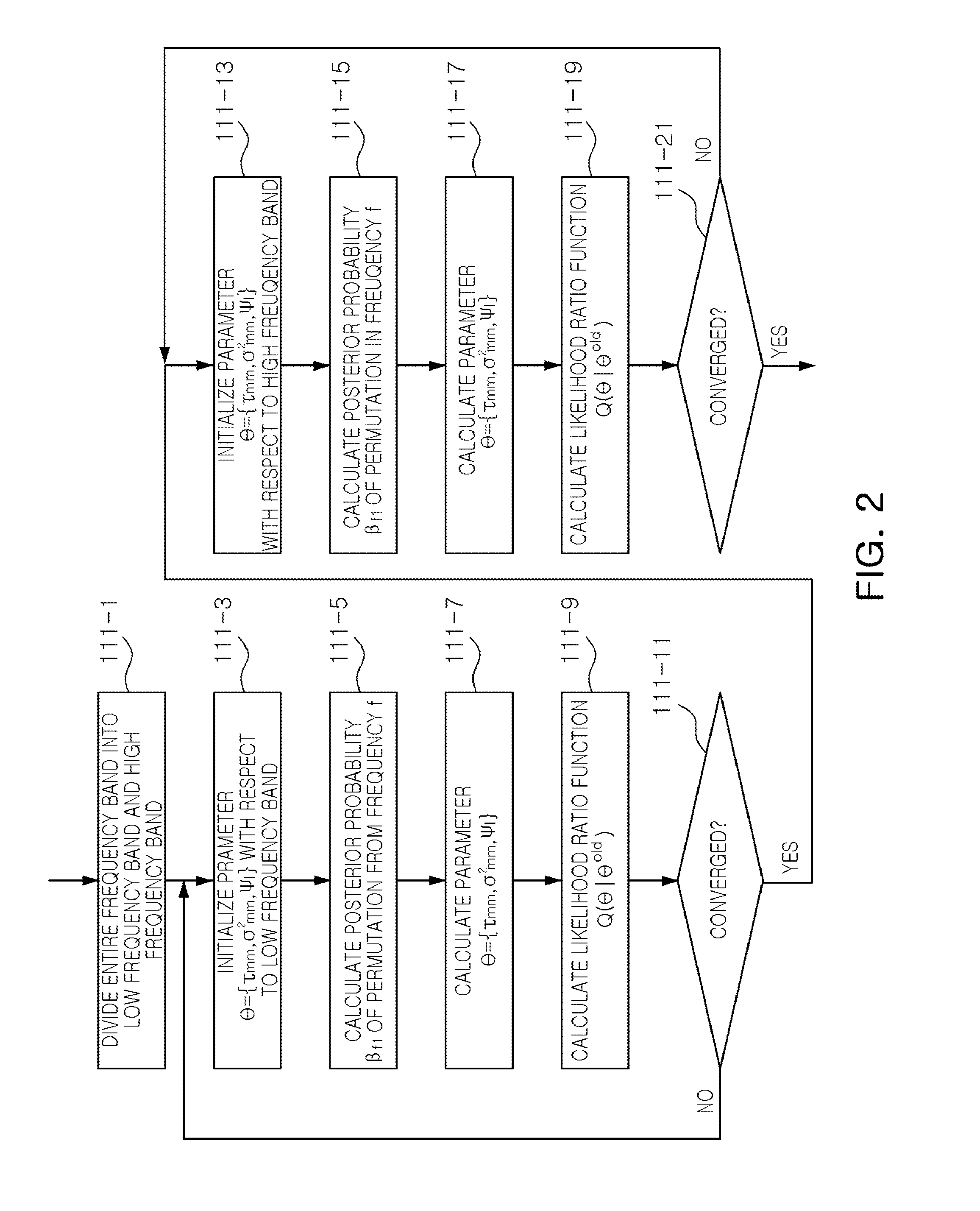
[0034]In the estimating of the time delay parameter, θ which maximizes a cost function of Equation of

Problems solved by technology

However, when spatial aliasing occurs due to a wide frequency band of a signal or due to a large space between sensors, because the k value has a value, not 0, a one-to-one corresponding relationship is not maintained between the direction information and phase information (or time delay information), so the method cannot be employed.
However, as the k-means clustering scheme does not utilize statistical characteristics, its performance may be degraded in an environment in which an echo is large or background noise is present.
However, because this method utilizes W(f) forming a spectrum zero point with respect to a signal source, it cannot be applied to a case in which there are three or more signal sources.
Also, this method does not consider statistical characteristics, the performance may be degraded in an area with excessive echo, and information regarding the size and disposition of a sensor array is required.

Method used


Image

  • Method for separating blind signal and apparatus for performing the same
  • Method for separating blind signal and apparatus for performing the same
  • Method for separating blind signal and apparatus for performing the same

Examples


Embodiment Construction

[0047]The present invention will now be described more fully hereinafter with reference to the accompanying drawings, in which preferred embodiments of the invention are shown.

[0048]However, it should be understood that the following exemplifying description of the invention is not meant to restrict the invention to specific forms of the present invention but rather the present invention is meant to cover all modifications, similarities and alternatives which are included in the spirit and scope of the present invention. The terms used in the present application are merely used to describe particular embodiments, and are not intended to limit the present invention. Unless otherwise defined, all terms used herein, including technical or scientific terms, have the same meanings as those generally understood by those with ordinary knowledge in the field of art to which the present invention belongs. Such terms as those defined in a generally used dictionary are to be interpreted to hav...


PUM


Abstract

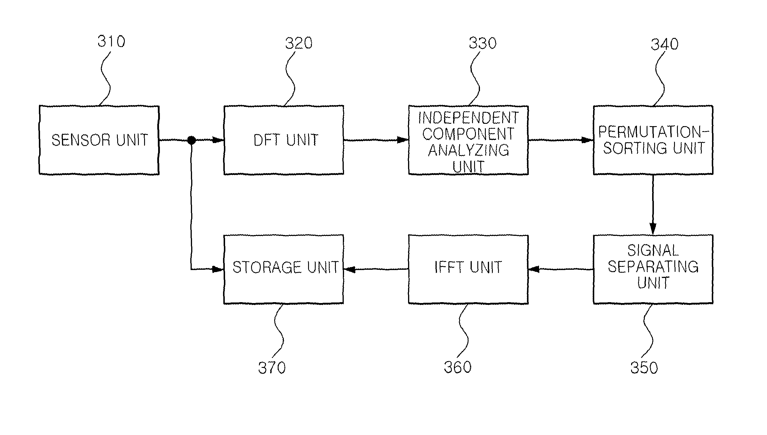
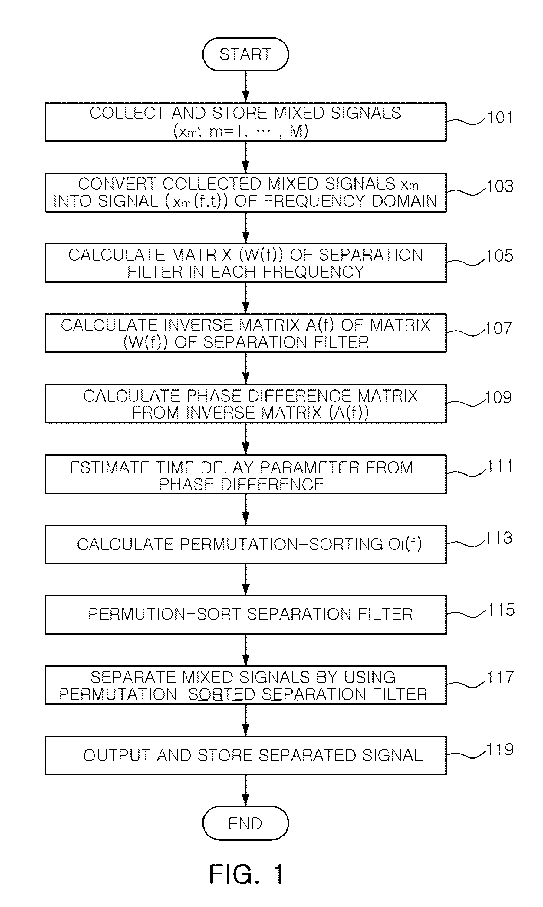
A method for separating a blind signal includes: converting mixed signals of a time domain collected by using a plurality of sensors into mixed signals of a frequency domain; calculating a separation filter from the mixed signals which have been converted into those of the frequency domain; calculating an inverse filter of the separation filter; calculating the difference in phase between the respective sensors from the calculated inverse filter; permutation-sorting the separation filter by using the calculated phase difference; and separating the mixed signals of the frequency domain by using the permutation-sorted separation filter.

Description

CROSS-REFERENCE TO RELATED APPLICATIONS[0001]This application claims the priority of Korean Patent Application Nos. 10-2009-0127541 filed on Dec. 18, 2009 and 10-2010-0104197 filed on Oct. 25, 2010, in the Korean Intellectual Property Office, the disclosures of which are incorporated herein by reference.BACKGROUND OF THE INVENTION[0002]1. Field of the Invention[0003]The present invention relates to a signal processing technique and, more particularly, to a blind signal separating method for separating respective signals from multi-channel multi-path mixed signals, and an apparatus for performing the same.[0004]2. Description of the Related Art[0005]In general, a plurality of signal sources in a multi-channel multi-path environment reach respective sensors via various paths and are mixed in the respective sensors. Among the various paths from the locations of the signal sources to the sensors, a direct path involves a time delay corresponding to relative locations of the signal sourc...

Claims


Application Information

Patent Timeline
Patent Type & Authority Patents(United States)
IPC IPC(8): H04B15/00
CPCG10L21/0272G10L2021/02166
Inventor NAM, SEUNG HYON
Owner ELECTRONICS & TELECOMM RES INST
Learn More