
Detector and detection method for a capacitive touchpad to identify a real touch point

a capacitive touchpad and detection method technology, applied in the field of capacitive touchpads, can solve problems such as ineffective multi-touch applications

Active Publication Date: 2013-08-27
ELAN MICROELECTRONICS CORPORATION
View PDF8 Cites 24 Cited by
  • Summary
  • Abstract
  • Description
  • Claims
  • Application Information

AI Technical Summary

Benefits of technology

The present invention aims to provide a simple detector for a capacitive touchpad that can identify a real touch point. This invention also provides a simple method for identifying a real touch point on a capacitive touchpad.

Problems solved by technology

However, such methods can only detect a single touch point each time, but cannot be effective for multi-touch applications.

Method used


Image

  • Detector and detection method for a capacitive touchpad to identify a real touch point
  • Detector and detection method for a capacitive touchpad to identify a real touch point
  • Detector and detection method for a capacitive touchpad to identify a real touch point

Examples


first embodiment

[0046]FIG. 5 is the circuit diagram of a first embodiment according to the present invention to carry out the process of FIG. 4, in which a detector 50 is used to scan the capacitance sensor traces TX1-TXN and TY1-TYM of a capacitive touchpad for identifying any real touch point. Multiplexers 52 and 54 are used to select from the capacitance sensor traces TX1-TXN and TY1-TYM to connect to the detector 50 for being detected for capacitance therefrom. In the detector 50, a switching circuit 56 includes switches SW2, SW3 and SW4 connected between the output terminal of the multiplexer 52 and nodes having supply voltages VREFP, VCOM and VREFN, respectively, and is thereby controlled to apply one of the supply voltages VREFP, VCOM and VREFN to the output terminal of the multiplexer 52. A switch SW1 is further connected between the output terminal of the multiplexer 52 and a self negative capacitance compensator 58 which is used to compensate the detected capacitance sensor trace when det...

second embodiment

[0063]FIG. 23 is the circuit diagram of a second embodiment according to the present invention. Similar to that shown in FIG. 5, the detector 130 in this embodiment includes the nodes having the supply voltages VREFP, VCOM and VREFN, the switching circuit 56, the self negative capacitance compensator 58, the mode switching device 60, the ADC 72, and the MCU 74. In addition to the operational amplifier 64, the gain control capacitor array CF, the storage capacitor array CS and the switch SW6, the sensing circuit 132 of the detector 130 further includes a switching circuit 134. The terminal 78 of the gain control capacitor array CF is connected to the voltage source VCOM or the output terminal 70 of the operational amplifier 64 depending on the switching circuit 134 which has a switch SW7 connected between the terminal 78 of the gain control capacitor array CF and the output terminal 70 of the operational amplifier 64, and a switch SW8 connected between the terminal 78 of the gain con...


PUM


Abstract

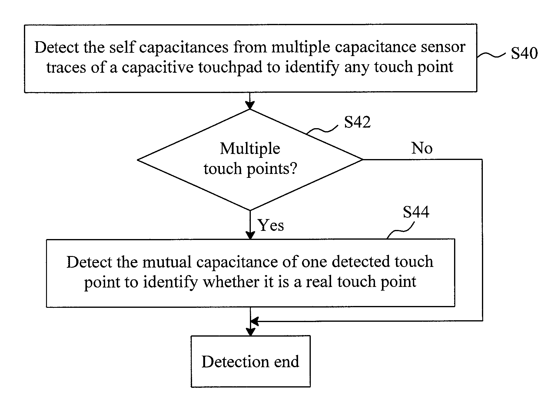
A two-step detection for a capacitive touchpad to identify a real touch point first detects the self capacitances from multiple capacitance sensor traces of the capacitive touchpad to identify any touch point on the capacitive touchpad and then, if multiple touch points are detected, further detects the mutual capacitance at one of the detected touch points to identify whether it is a real touch point.

Description

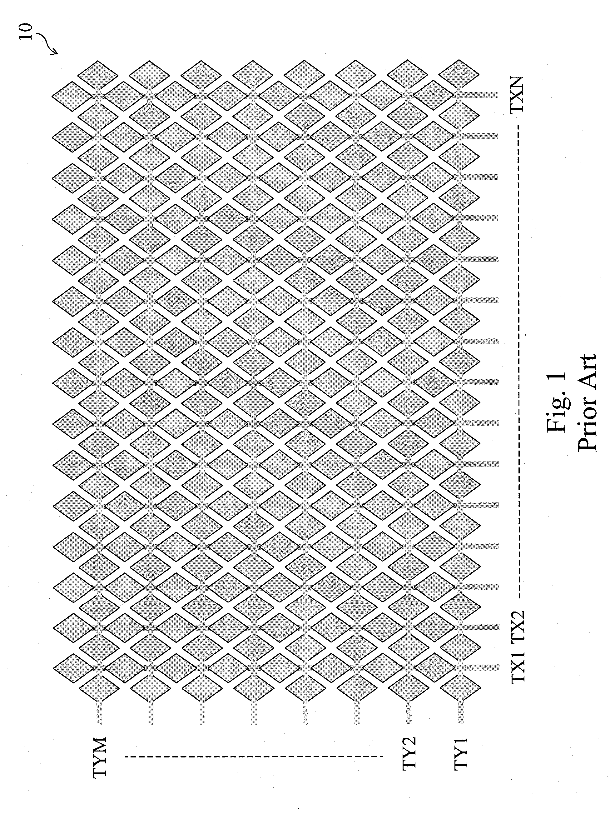
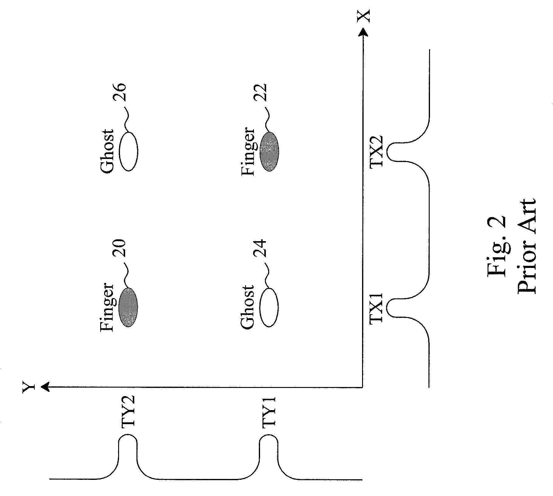
FIELD OF THE INVENTION[0001]The present invention is related generally to capacitive touchpads and, more particularly, to a detector and method for a capacitive touchpad to identify a real touch point.BACKGROUND OF THE INVENTION[0002]FIG. 1 is a simplified diagram showing the layout of a conventional two-dimensional capacitive touchpad 10 which includes capacitance sensor traces TX1-TXN in X-direction and TY1-TYM in Y-direction. For such capacitive touchpad 10, conventional methods for touch point detection is to detect the self capacitance from each of the capacitance sensor traces TX1-TXN and TY1-TYM, and then the position at which the detected capacitance has the maximum variation is determined as the touch point. However, such methods can only detect a single touch point each time, but cannot be effective for multi-touch applications. For example, as shown in FIG. 2, when two fingers touch the capacitive touchpad 10 simultaneously, in addition to the real touch points 20 and 22,...

Claims


Application Information

Patent Timeline
Patent Type & Authority Patents(United States)
IPC IPC(8): G06F3/045
CPCG06F3/0416G06F3/044G06F2203/04104G06F3/0446G06F3/041662G06F3/04186G06F3/04166
Inventor HUANG, CHUN-CHUNGWANG, TSUN-MINCHIU, TE-SHENG
Owner ELAN MICROELECTRONICS CORPORATION
Learn More