Magneto generator with multiple sets of three-phase windings

a three-phase winding and magneto coil technology, which is applied in the direction of windings, synchronous generators with multiple outputs, rotating magnets, etc., can solve the problems of low power generation efficiency of the magneto coil formed of the winding portions, and large axial dimension of the stator having the magneto coil wound around the stator core, so as to improve the operating efficiency and small size

Inactive Publication Date: 2013-08-27
MITSUBISHI ELECTRIC CORP
View PDF32 Cites 10 Cited by
  • Summary
  • Abstract
  • Description
  • Claims
  • Application Information

AI Technical Summary

Benefits of technology

[0009]Accordingly, the present invention is intended to obviate the problems as referred to above, and has for its object to obtain a rotating electrical machine which can be made small in size and light in weight, and can be improved in the operating efficiency thereof.
[0012]According to the present inventor, it is possible to make a three-phase rotating electrical machine small in size and light in weight as well as to improve the operating efficiency thereof.

Problems solved by technology

In the case of the winding portions constructed in such a distributed winding, the conductors protrude from an end face of the stator core to stride over the nine slots to extend to the following slot, thus posing the following problem.
That is, the circumferential length of the conductors becomes long, so the weight thereof is heavy and the electric resistance of the winding portions increases, resulting in low power generation efficiency of the magneto coil formed of the winding portions.
In addition, the height of a coil end of the magneto coil protruding from an end face of the stator core is high, so there is also another problem that the axial dimension of a stator having the magneto coil wound around the stator core is large.

Method used


Image

  • Magneto generator with multiple sets of three-phase windings
  • Magneto generator with multiple sets of three-phase windings
  • Magneto generator with multiple sets of three-phase windings

Examples


embodiment 1

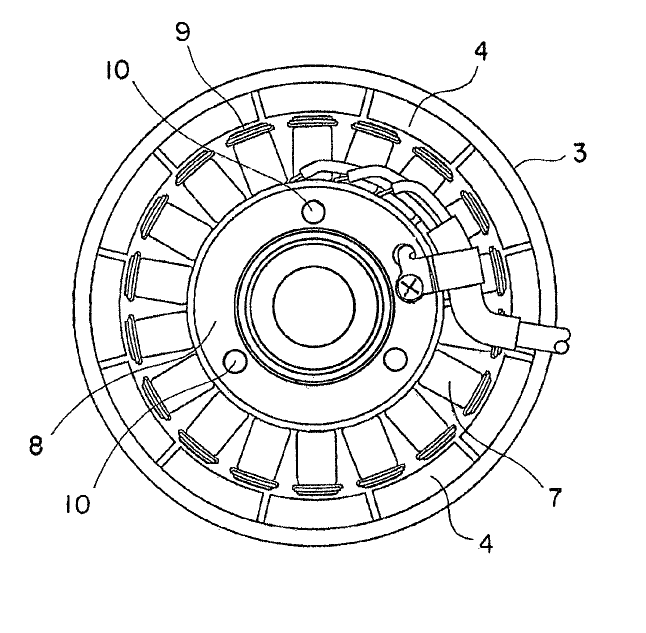
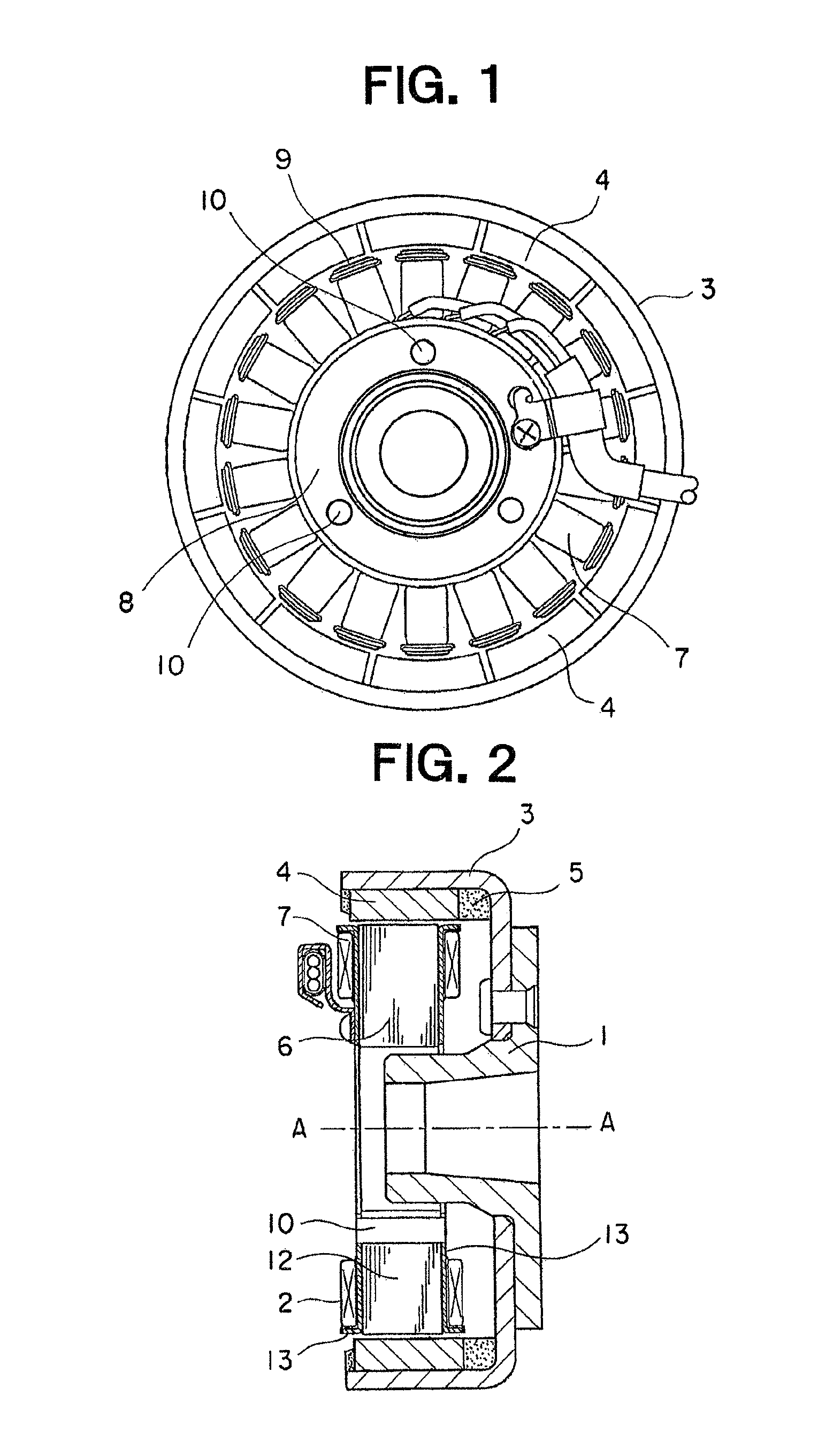
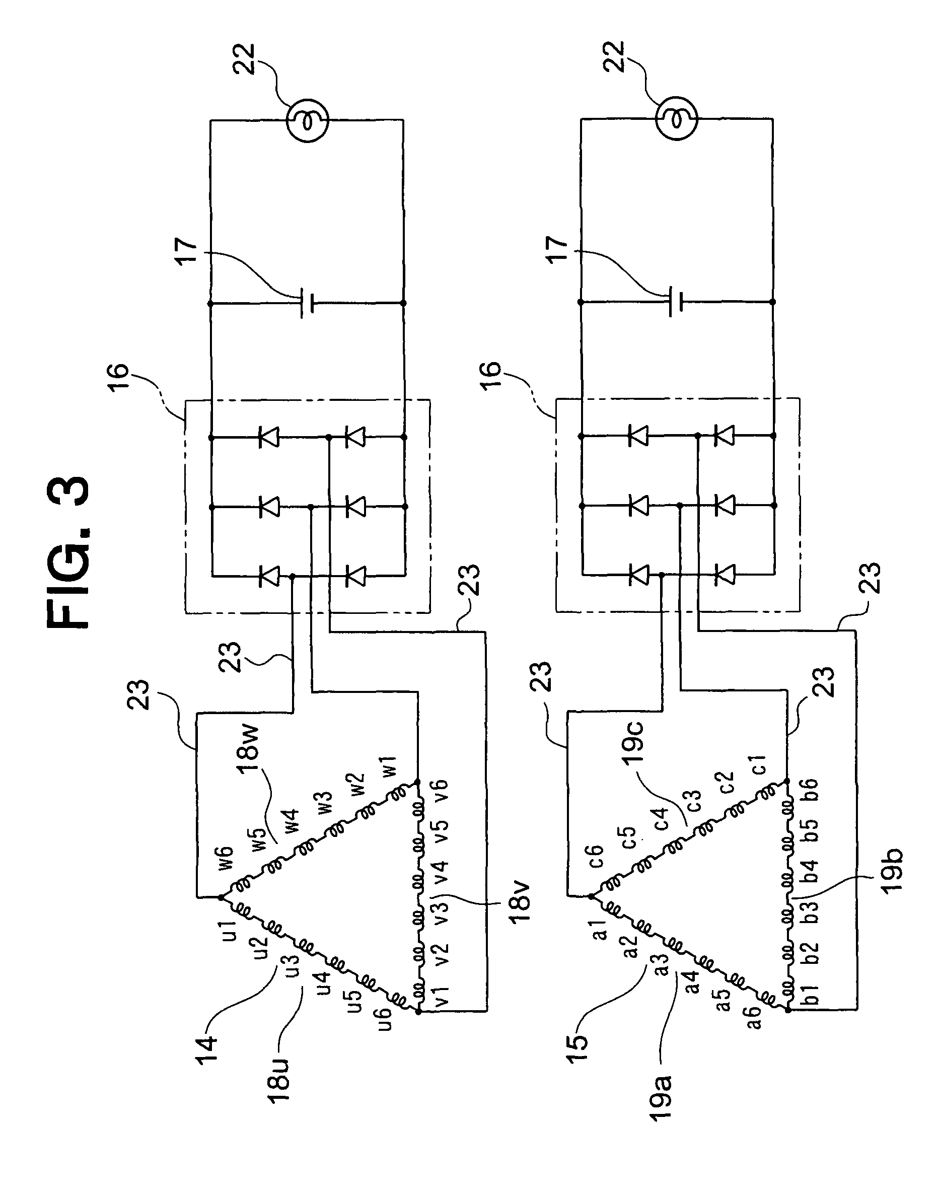
[0026]Referring to the drawings and first to FIG. 1, there is shown, in a front elevational view, a magneto generator according to a first embodiment of the present invention. FIG. 2 is a cross sectional side elevational view of the magneto generator of FIG. 1, and FIG. 3 is an electric circuit diagram of the magneto generator of FIG. 1.

[0027]This magneto generator, serving as a rotating electric machine, is provided with a rotor 1 operatively connected with an internal combustion engine, and a stator 2 disposed at an inner side of the rotor 1.

[0028]The rotor 1 has a bowl-shaped flywheel 3 and a plurality of permanent magnets 4 fixedly attached to an inner wall surface of the flywheel 3. The rotor 1 rotates about an axis of rotation A-A.

[0029]The permanent magnets 4 are fixedly attached to an inner peripheral surface of a cylindrical portion of the flywheel 3 at equal angular intervals with respect to one another around the axis of rotation A-A by means of molding members 5 (omitted...

embodiment 2

[0054]FIG. 9 is a front elevational view showing essential portions of a magneto generator according to the second embodiment of the present invention, and FIG. 10 is a cross sectional arrow view along line X-X of FIG. 9.

[0055]In this second embodiment, of three-phase windings, a first three-phase winding 14 is wound or arranged at an outer diameter side, and a second three-phase winding 15 is wound or arranged at an inner diameter side. The other construction of this second embodiment is similar to that of the first embodiment.

[0056]In this second embodiment, the first three-phase winding 14 is arranged at the outer diameter side, and the second three-phase winding 15 is arranged at the inner diameter side, with the different conductors of the three-phase windings 14, 15 being concentratedly wound around the individual teeth 9, respectively. With such an arrangement, it becomes possible to freely set the positions of the starting point and the ending point of each of the winding po...


PUM


Abstract

A magneto generator can be made small in size and light in weight, and improved in power generation efficiency. The magneto generator includes an iron core having an iron core main body and a plurality of teeth (9) radially extending from the iron core main body, and an armature having a first three-phase winding (14) and a second three-phase winding (15) comprising winding portions (18u, 18v, 18w, 19a, 19b and 19c) of individual phases wound around the stator core. The individual first and second three-phase windings (14, 15) have the winding portions (18u, 18v, 18w, 19a, 19b and 19c) constructed by concentratedly winding conductors around the individual teeth (9), respectively, while skipping every predetermined number of teeth (9), and are wound in a state divided into an inner layer side and an outer layer side, respectively.

Description

BACKGROUND OF THE INVENTION[0001]1. Field of the Invention[0002]The present invention relates to a three-phase rotating electrical machine such as for example a magneto generator with an armature having a plurality of three-phase windings wound around an iron core.[0003]2. Description of the Related Art[0004]In the past, there has been known a vehicular alternator with two three-phase windings wound in the same slots (see, for example, a first patent document: Japanese patent application laid-open No. 2006-87248 (paragraph No. [0028] on page 7 and FIG. 2).[0005]In this vehicular alternator, the winding portions of the individual phases constituting the three-phase windings have conductors wound up in a waveform beforehand, and are inserted into slots formed between adjacent ones of a plurality of teeth arranged to radially extend from an iron core main body so as to be wound around a fixed stator core.[0006]In this vehicular alternator, the winding portions are wound around the stat...

Claims


Application Information

Patent Timeline
Patent Type & Authority Patents(United States)
IPC IPC(8): H02K1/00H02K19/00H02K17/00H02K3/00H02K21/00H02K27/02H02K23/26H02K3/28
CPCH02K3/18H02K3/28H02K21/48H02K21/22
Inventor BABA, SHINJI
Owner MITSUBISHI ELECTRIC CORP
Why Eureka
Try Eureka