
Bicycle pedal assembly

a pedal assembly and bicycle technology, applied in the field of bicycles, can solve the problems of difficult to achieve the effect of pedal rotation

Inactive Publication Date: 2013-08-27
ANIMAL BIKES
View PDF34 Cites 9 Cited by
  • Summary
  • Abstract
  • Description
  • Claims
  • Application Information

AI Technical Summary

Benefits of technology

[0010]As to a further aspect of the invention, the pedal body is restricted from movement in the longitudinal direction between the inner surface of the shoulder and the outer surface of the restricting member. This prevents longitudinal motion of the pedal body along the pedal shaft without assistance of any fasteners, while promoting the rotational motion of the pedal on the shaft.

Problems solved by technology

It is not uncommon for such independent fasteners to become loose, causing failure and malfunction of the entire pedal assembly.
Furthermore, the prior art methods of assembly of the pedal units are often quite complex, laborious and require special tools.

Method used


Image

  • Bicycle pedal assembly
  • Bicycle pedal assembly
  • Bicycle pedal assembly

Examples


Embodiment Construction

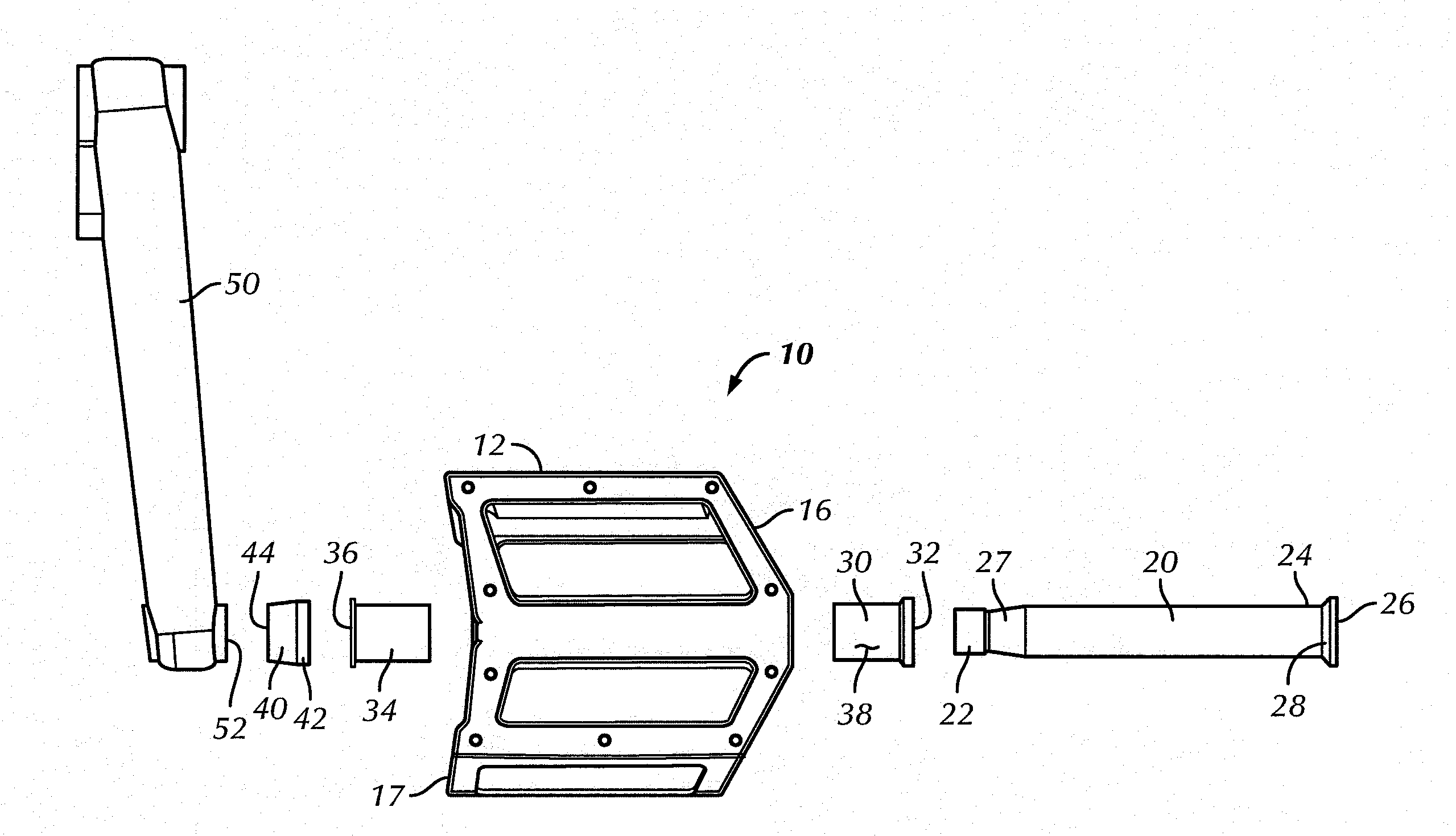
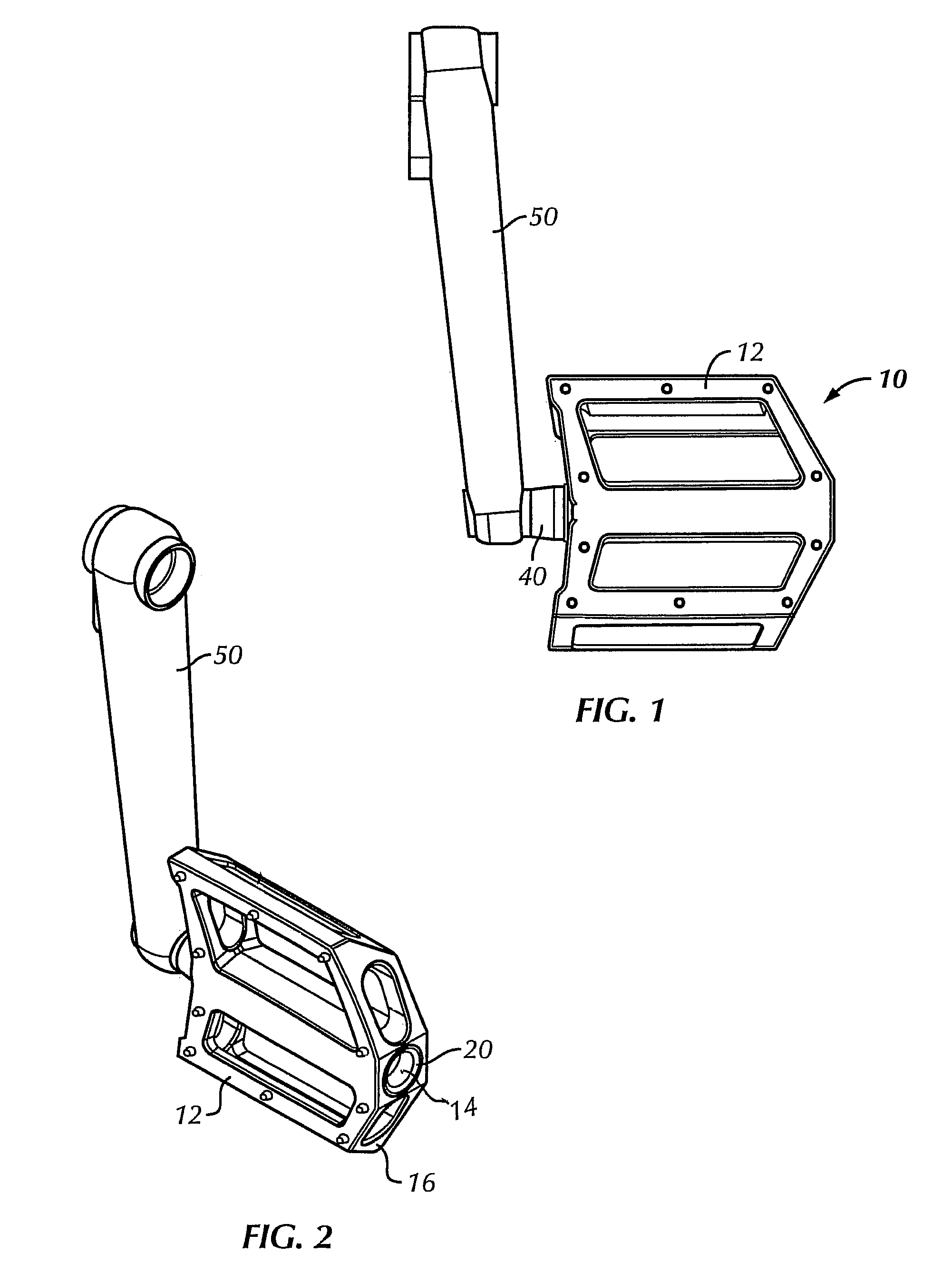
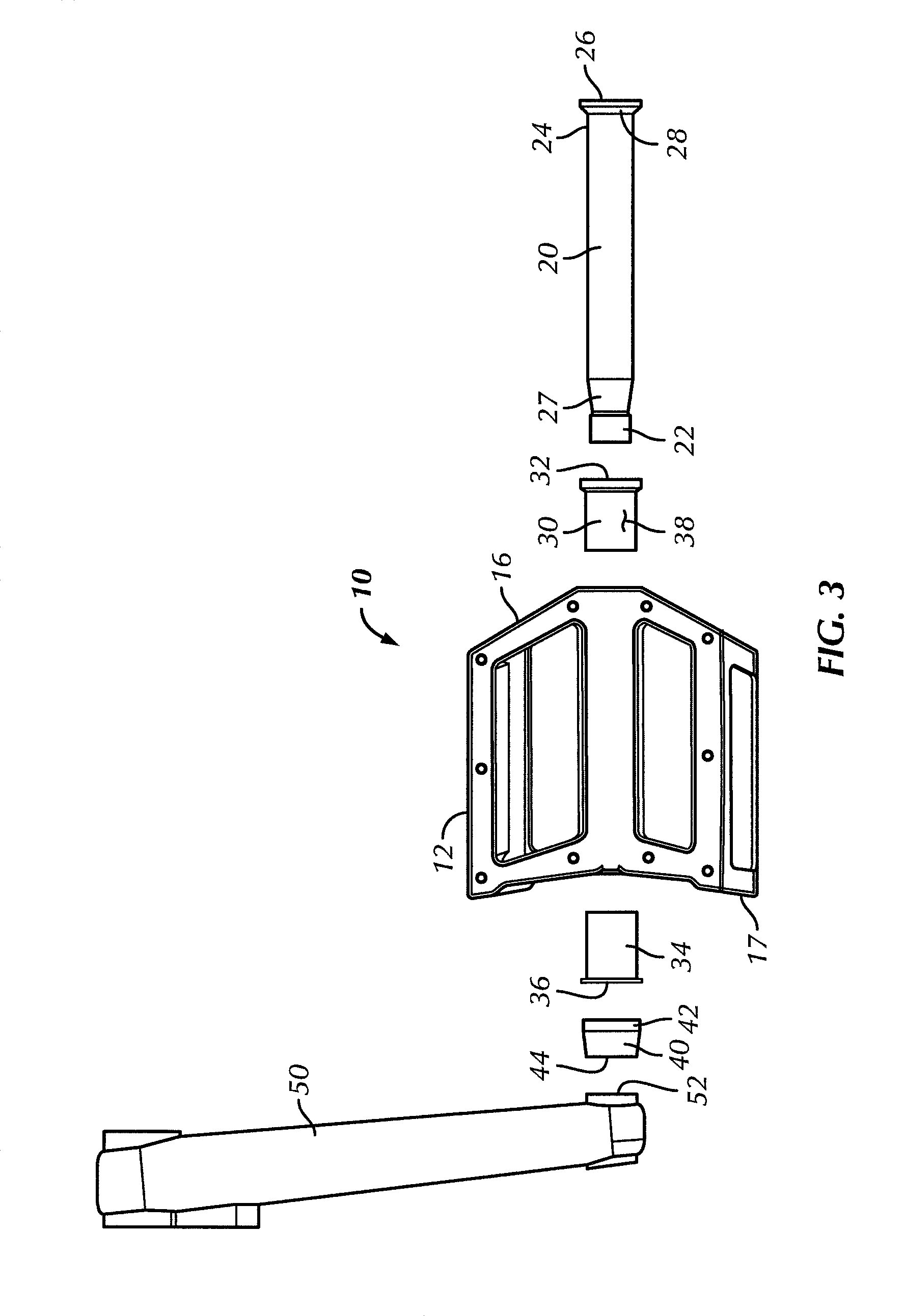
[0022]Referring now to the drawings in general, and to FIGS. 1-5 specifically, illustrating a first embodiment of the bicycle pedal assembly 10. The invention provides a bicycle pedal assembly 10 comprising a pedal body 12 for supporting a foot of a cyclist which is rotatably coupled to the pedal shaft or spindle 20 for rotation about a longitudinal axis of the shaft. Typically, the pedal shaft or spindle 20 is substantially hollow. However, a solid or semi-solid pedal shaft is also contemplated. The pedal body 12 is formed with an inboard end 17 and an outboard end 16. The pedal body has a bore or aperture 14, extending from the inboard end to the outboard end, for rotatably receiving the pedal shaft or spindle 20. The pedal shaft 20 has a first end 22 threadably or fixedly coupled to a bicycle crank arm 50 for rotation therewith and a second end 24.

[0023]Referring now to FIGS. 1-5 and 9, where one embodiment of the pedal shaft or spindle 20 will be discussed in more detail. The fi...


PUM

PropertyMeasurementUnit
areaaaaaaaaaaa
radial areaaaaaaaaaaa
movementaaaaaaaaaa

Abstract

A bicycle pedal assembly having a pedal body rotatably coupled to a pedal shaft. A bore receiving the pedal shaft passes through the pedal body. A semi-cylindrical shoulder extends outwardly from an exterior surface of the shaft. A bushing is positioned within the bore to rotatably support the pedal shaft. An inner surface of the shoulder rotatably engages the external end of the bushing, so that the second end of the shaft is movably connected to the pedal body without assistance of any fasteners.

Description

[0001]This application claims priority of U.S. Provisional Application Ser. No. 61 / 455,105 filed Oct. 14, 2010, which application is being incorporated by reference in its entirety.FIELD OF INVENTION[0002]The invention relates to bicycles in general, more specifically it relates to bicycle pedals and methods of their assembly.DISCUSSION OF THE PRIOR ART[0003]It is well known that the bicycle pedal assemblies of the prior art often require various fasteners for keeping the assemblies together. For example, in the prior art independent fasteners are typically required for securing the pedal body on the pedal shaft or spindle. It is not uncommon for such independent fasteners to become loose, causing failure and malfunction of the entire pedal assembly.[0004]Furthermore, the prior art methods of assembly of the pedal units are often quite complex, laborious and require special tools. This is because, the body of the pedal is typically positioned or inserted on the spindle from the oute...

Claims


Application Information

Patent Timeline
Patent Type & Authority Patents(United States)
IPC IPC(8): B62M3/00
CPCB62M3/08Y10T74/2164Y10T29/49826Y10T74/2168
Inventor CURRAN, SEANLAM, FRANK
Owner ANIMAL BIKES
Learn More