Supercharge Your Innovation With Domain-Expert AI Agents!

Thermistor and method for manufacturing the same

a technology of thermistor and thin film layer, which is applied in the direction of positive temperature coefficient thermistors, instruments, heat measurement, etc., can solve the problems of difficult cracking in the thin film layer portion of the thermistor, and achieve the effect of reducing the height or mounting height, reducing the cost and minimal spa

Active Publication Date: 2013-08-20
MURATA MFG CO LTD
View PDF23 Cites 3 Cited by
  • Summary
  • Abstract
  • Description
  • Claims
  • Application Information

AI Technical Summary

Benefits of technology

[0007]It is an object of the present invention to provide a thermistor which can be mounted by reflow and can be mounted on a minimal space and a method for manufacturing the same. It is another object of the invention to provide a thermistor in which a reduction in the height can be achieved and the occurrence of cracking can be suppressed as much as possible and which can be manufactured at a low cost and a method for manufacturing the same.
[0013]In the manufacturing method, since the thermistor thin film layer is formed by a solid phase method, the thermistor thin film layer can be manufactured at a lower cost than that of a case where the thermistor thin film layer is manufactured by a gas phase method and also since the metal base material, the thermistor thin film layer, and the split electrodes are integrally fired, the occurrence of cracking in the metal base material or the thermistor thin film layer can be suppressed as much as possible.
[0014]According to the present invention, a thermistor can be obtained in which a reduction in the height or mounting by reflow can be achieved and which can be mounted on a minimal space. Moreover, since the thermistor thin film layer is formed by a solid phase method, the thermistor thin film layer can be manufactured at a low cost and the occurrence of cracking can be suppressed as much as possible by integrally firing.

Problems solved by technology

Therefore, even when a stress is applied to a thermistor, cracking is hard to occur in a thermistor thin film layer portion.

Method used


Image

  • Thermistor and method for manufacturing the same
  • Thermistor and method for manufacturing the same
  • Thermistor and method for manufacturing the same

Examples


first example

FIGS. 1 to 3

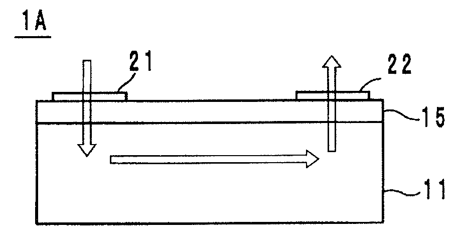
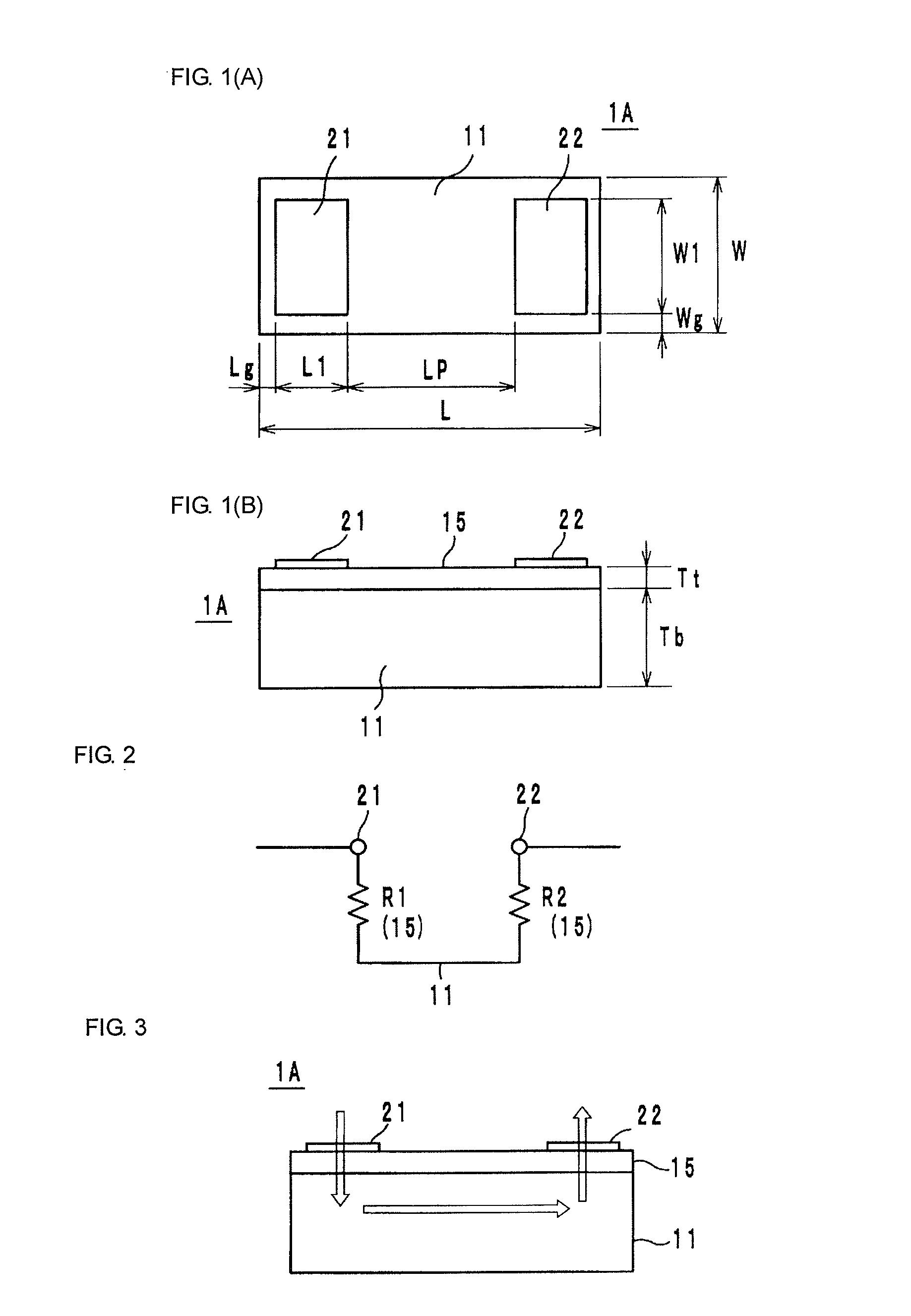
[0024]As illustrated in FIG. 1, an NTC thermistor 1A which is a first example is constituted by a metal base material 11, a thermistor thin film layer 15 formed on the metal base material 11, and a pair of split electrodes 21 and 22 formed on the thermistor thin film layer 15. The metal base material 11 is formed into a sheet shape from a metal powder paste. The thermistor thin film layer 15 is formed into a sheet shape from a ceramic slurry. The split electrodes 21 and 22 are obtained by forming an electrode material paste into a predetermined shape. These three substances are integrally fired. At least the metal base material 11 and the thermistor thin film layer 15 may be fired.

[0025]The thickness of the metal base material 11 is about 10 to 80 μm. The thickness of the thermistor thin film layer 15 is about 1 to 10 μm. The thickness of the split electrodes 21 and 22 is about 0.1 to 10 μm. The thickness as the entire thermistor 1A is about 10 to 100 μm. Herein, the ent...

second example

[0054]As a second example, thermistors having the same configuration as that of the first example and having Tb=30 μm, L=600 μm, W=300 μm, L1=200 μm, W1=260 μm, Lg=20 Wg=20 μm, Lp=160 μm, and Tt=5 μm were produced by preparing materials shown in Tables 6 and 7 and by the same manufacturing process as the above-described manufacturing process. The coefficient of linear expansion shown in Tables 6 and 7 are the results of manufacturing a square column having a cross section of 2.0 mm×2.0 mm and a length of 5.0 mm from a material of the metal base material and a material of the thermistor thin film, and measuring the coefficient of linear expansion by TMA in the air atmosphere. The value of the coefficient of linear expansion at 800° C. is indicated on the basis of 30° C. With respect to the measurement conditions, the temperature elevation rate was 10° C. / min and a load was 10 gf.

[0055]

TABLE 6Material ofCoefficient of linear metal base materialexpansion (×10−5 / K)Ag: 1001.93Ag: 80, Pd:...

third example

FIG. 5

[0060]Similarly as in the first example above, an NTC thermistor 1B which is a third example has the metal base material 11, the thermistor thin film layer 15, and the split electrodes 21 and 22 as illustrated in FIG. 5, and, in addition, a protection layer 16 is formed on the thermistor thin film layer 15 and an Ni plating layer 23 and an Sn plating layer 24 are formed on the split electrodes 21 and 22.

[0061]An Ni plating layer 23′ and an Sn plating layer 24′ are formed also on the surface of the metal base material 11. However, the layers are formed simultaneously with the formation of the plating layers 23 and 24. By these plating layers 23′ and 24′, an effect of preventing the migration of Ag can be expected when the metal base material 11 is Ag / Pd or the like.

[0062]The protection layer 16 is one which suppresses the corrosion of the thermistor thin film layer 15 by plating in the formation of the plating layers 23 and 24 and which may be an insulator material, such as gla...


PUM

PropertyMeasurementUnit
thicknessaaaaaaaaaa
thicknessaaaaaaaaaa
distanceaaaaaaaaaa

Abstract

An NTC thermistor having a metal base material, a thermistor film layer formed on the metal base material, and a pair of split electrodes formed on the thermistor film layer. A ceramic slurry is applied onto a carrier film to form the thermistor film layer, a metal powder containing paste is applied onto the thermistor film layer to form the metal base material, and further an electrode paste is applied onto the metal base material to form the split electrodes. Thereafter, the three substances are integrally fired.

Description

CROSS REFERENCE TO RELATED APPLICATIONS[0001]The present application is a divisional of application Ser. No. 13 / 404,094, filed Feb. 24, 2012, which is a continuation of International application No. PCT / JP2010 / 064089, filed Aug. 20, 2010, which claims priority to Japanese Patent Application No. 2009-198024, filed Aug. 28, 2009, the entire contents of each of which are incorporated herein by reference.FIELD OF THE INVENTION[0002]The present invention relates to a thermistor and a method for manufacturing the same, and particularly relates to a thermistor in which a metal base material, a thermistor thin film layer, and an electrode are laminated and a method for manufacturing the same.BACKGROUND OF THE INVENTION[0003]As an NTC thermistor or a PTC thermistor used as a temperature sensor or the like in a protection circuit heretofore, one disclosed in Patent Document 1 is known. The thermistor has a plate-like metal substrate which also serves as an electrode, a themosensitive resistor...

Claims


Application Information

Patent Timeline
Patent Type & Authority Patents(United States)
IPC IPC(8): H01C7/10
CPCG01K7/22H01C1/1413H01C7/04H01C17/30H01C17/00H01C17/065Y10T29/49085H01C1/142H01C7/008H01C17/281
Inventor MIURA, TADAMASA
Owner MURATA MFG CO LTD
Features
  • R&D
  • Intellectual Property
  • Life Sciences
  • Materials
  • Tech Scout
  • Unparalleled Data Quality
  • Higher Quality Content
  • 60% Fewer Hallucinations
Learn More