
Luminaire

Active Publication Date: 2013-08-20
BEGA GANTENBRINK LEUCHTEN
View PDF18 Cites 3 Cited by
  • Summary
  • Abstract
  • Description
  • Claims
  • Application Information

AI Technical Summary

Benefits of technology

The present invention aims to provide a cost-effective luminaire that is suitable for street and path lighting. The new luminaire should overcome the shortcomings of previous designs by simplifying manufacturing and reducing glare for observers.

Problems solved by technology

This arrangement of light-emitting diodes in a street lighting is, on the one hand, disadvantageous insofar as the light-emitting diodes illuminate the target surface directly and are therefore also directly visible.
This leads to a strong glare for an observer.
Since the light-emitting diodes or the groups of light-emitting diodes are individually oriented onto points of the target surface, a very complex geometry of the mechanical structure of the luminaire is required.
This results in a high manufacturing outlay and therefore also in high costs of the overall system.
Hence, also the repair of the light-emitting diode unit entails great effort and high costs.
Another drawback is to be seen in the collimators which are frequently used for concentrating the light of the light-emitting diodes.
The collimators have a comparatively low efficiency amounting in some cases only to approx.
Street lightings having the above-described structural design are therefore often inefficient.
Another drawback is to be seen in the fact that most collimators operate on the basis of the principle that the light emitted by the light-emitting diode is totally reflected by the circumferential surface of the collimators.
If water droplets or condensed moisture adheres to the circumferential of surface the collimators, the collimators will be rendered ineffective.
Hence, street lightings in which the ancillary optics of the light-emitting diodes consist of collimators tend to be failure prone in the case of an ingress of moisture.
A street lighting of this kind is, on the one hand, disadvantageous insofar as it will normally not be possible to generate the ideal-typical luminosity distributions of a street lighting.
This variant is not very desirable for use as street lighting.
In addition, the efficiency of such a system must be considered rather low.

Method used


Image

  • Luminaire
  • Luminaire
  • Luminaire

Examples


Embodiment Construction

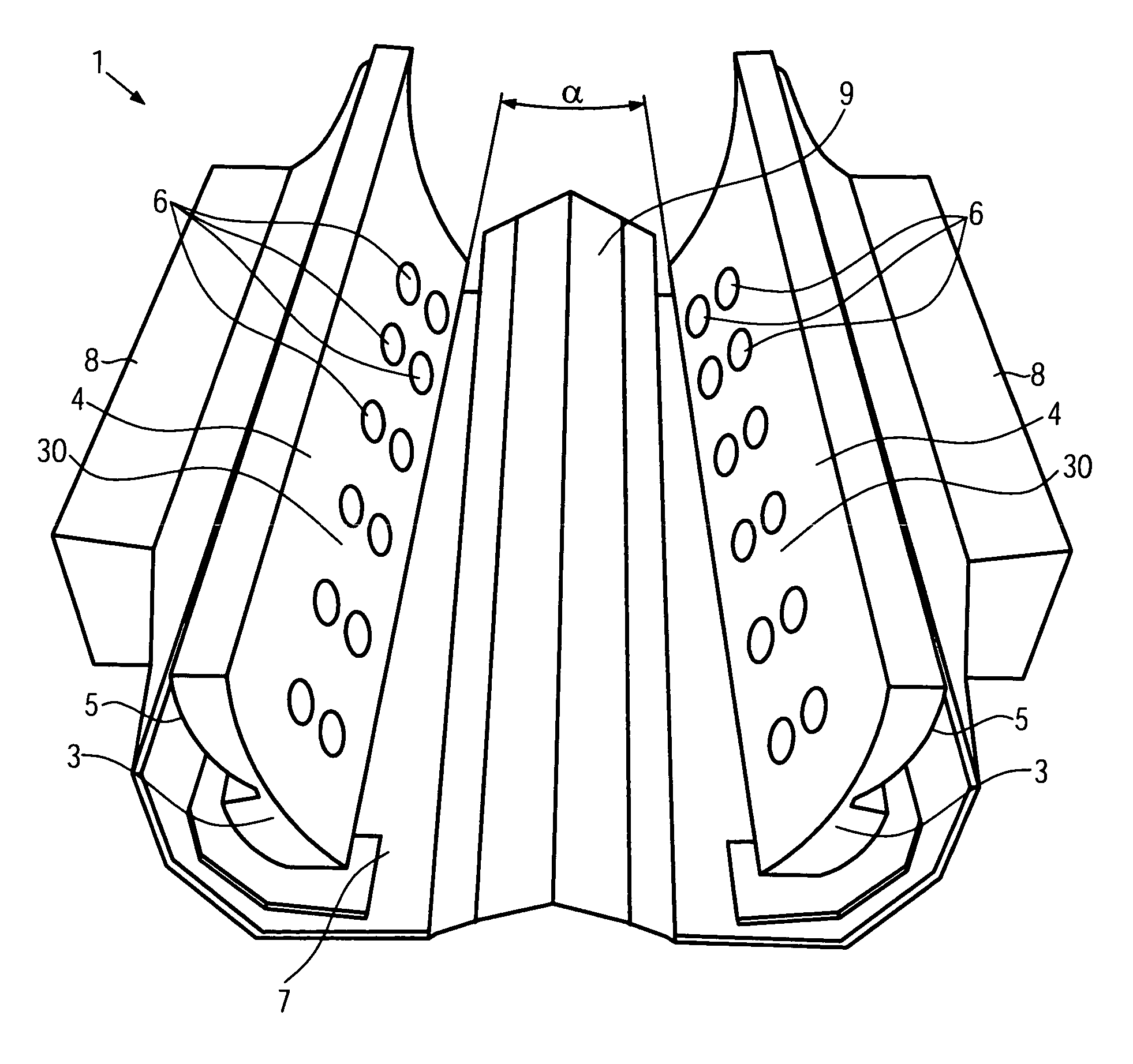
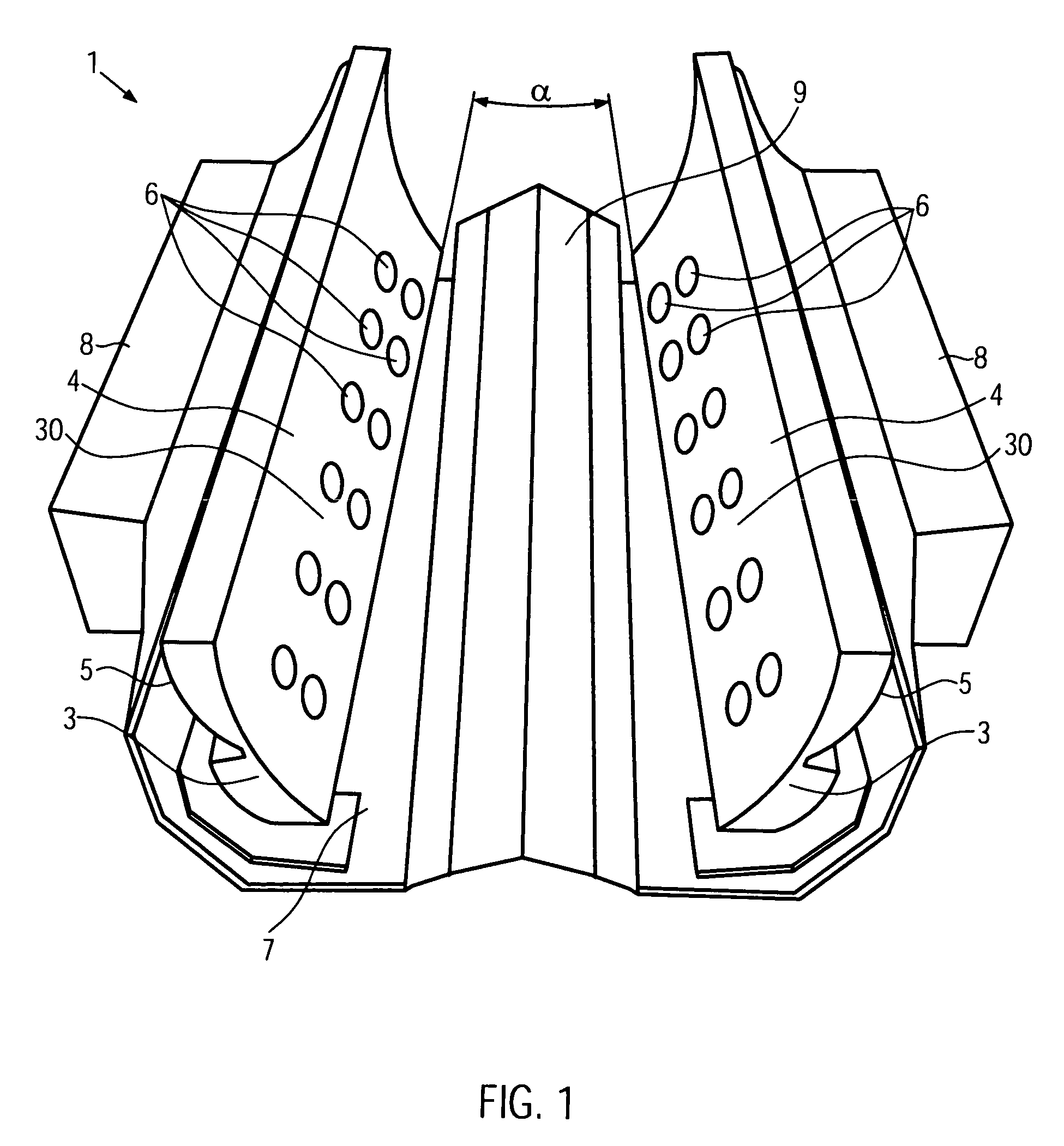
[0042]FIG. 1 shows a perspective view of a luminaire 1 from below. The luminaire 1 shown comprises two reflector profiles 3 extending linearly in the longitudinal direction. The two reflector profiles 3 extend, at least partially, in opposed relationship with one another and have an identical structural design. Each reflector profile 3 has a front 30 facing the interior of the luminaire 1 and a back 5 facing away from the front 30. The front 30 of the reflector profiles 3 is configured as a reflector surface 4 at least in certain areas thereof. To this end, the front 30 is provided with light-directing surfaces. The surface of the front 30 of the reflector profiles 3 may, for example, have evaporated thereon reflecting layers so as to form the reflector surfaces 4. It can be provided that the reflector surfaces 4 are slightly roughened, whereby the visible luminance in the luminaire 1 is reduced and the visual comfort increased.

[0043]Each of the reflector profiles 3 is provided with...


PUM


Abstract

A luminaire including a plurality of light-emitting light sources is provided. The luminaire can be produced with little manufacturing out-lay and, consequently, economically, which is suited for street and path lighting and reduces the glare for an observer. The luminaire comprises at least one reflector profile extending in the longitudinal direction and comprising a plurality of apertures and at least one reflector surface provided on the front of the reflector profile, the light sources being arranged in the area of the apertures at the back of the reflector profile. A reflector profile for a luminaire is also provided.

Description

CROSS-REFERENCE TO RELATED APPLICATIONS[0001]This application is a National Stage of International Patent Application No. PCT / EP2009 / 002799, filed on Apr. 16, 2009, which claims priority to foreign Patent Application No. DE 10 2008 033 533.9, filed on Jul. 17, 2008, the contents of which are incorporated herein by reference in their entirety.FIELD OF INVENTION[0002]The present invention relates to a luminaire comprising a plurality of light-emitting light sources.BACKGROUND OF THE INVENTION[0003]Light-emitting diodes (LEDs) have already been used for quite some time as light sources in luminaires. Light-emitting diodes are distinguished by low power consumption and a long service life. Meanwhile, it has also become known to use light-emitting diodes in street lightings. For this purpose, individual light-emitting diodes or groups of light-emitting diodes can be used. For influencing the emission characteristics of the light-emitting diodes, the latter are normally equipped with ligh...

Claims


Application Information

Patent Timeline
IPC IPC(8): F21V21/00
CPCF21S4/003F21V7/0008F21V7/0025F21V7/0083F21S2/005F21V7/005F21V7/06F21V19/001F21W2131/103F21Y2101/02F21S4/20F21Y2115/10
Inventor GANTENBRINK, HEINRICH JOHANNES
Owner BEGA GANTENBRINK LEUCHTEN
Learn More