Transponder, transponder kit, method of applying the transponder and product comprising the transponder

a technology of transponder and kit, which is applied in the field of transponder, transponder kit, method of applying the transponder and product comprising the transponder, can solve the problems of increasing the complexity of the marking process, requiring expensive special tools, and undesirable additional machining steps

Inactive Publication Date: 2013-08-20
TEKNOLOGIAN TUTKIMUSKESKUS VTT +1
View PDF12 Cites 5 Cited by
  • Summary
  • Abstract
  • Description
  • Claims
  • Application Information

AI Technical Summary

Benefits of technology

[0004]It is an aim of the invention to overcome the above problems and to achieve a novel type of RFID transponder which can be inserted into logs and other wood material. In particular, it is an aim to achieve a transponder and its application method removing the need of pre-processing of the log and to allowing for easy insertion and safe accommodation of the transponder in the log. It is also an aim to achieve a novel transponder insertion kit for the same purpose.
[0010]By means of the invention, the problems related both to patch-type transponders and nail-type transponders can be avoided. First, no preliminary machining of the wood is required, as the wedge-shaped edge of the transponder is capable of locally displacing wood in the vicinity of the wood surface and thus penetrating into the wood. Second, because the penetration depth of the transponder is significantly lower than that of nail-type transponders, the impact force can be kept at a reasonable level at least in proportion to impact area. In other words better support for the present transponder can be provided during insertion compared with nail-type transponders, preventing breaking of the transponder due to the impact force. Third, the present transponder geometry allows for the (dipole) antenna of the transponder to remain near the surface of the wood, making it easier to interrogate with.
[0011]According to one embodiment, the casing comprises one or more shoulders or recesses extending perpendicular to the insertion direction of the transponder from its sides for efficiently preventing disengagement of the transponder from the wood material after insertion. This is because after displacement of the wood material during penetration of the wedge-shaped part of the transponder, the resilient wood material expands as it tries to return to its original shape, thus locking the transponder firmly to the wood.
[0012]The kit according to the invention comprises a radio-frequency transponder of the above-described kind and an insertion tool shaped to intimately mate with at least considerable part of the second edge of the transponder casing such that the transponder can be guided with the insertion tool at least partly into the wood material. The transponder is preferably embedded entirely below the surface level of the wood material. After removal of the insertion tool, the resiliency of the wood locks the transponder to the wood. The insertion tool is preferably adapted to nestle against shoulders contained in the transponder for preventing breaking of the shoulders during insertion and for providing a larger contact area between the tool and the transponder. The structure also prevents woods fibres from getting between the tool and the transponder.
[0013]The insertion tool and the transponder preferably have a large common contact area in order to prevent cracking of the transponder during its insertion. That is, the insertion tool is preferably in contact with the transponder essentially over the whole length of the transponder. In a typical embodiment, the insertion tool comprises a recess or ridge the second edge of the casing of the transponder is designed to closely fit to. This helps the alignment if the transponder and the insertion tool, evens the pressure subjected to the transponder, and thus makes the marking process more robust.
[0021]According to one embodiment, the transponder is applied at the end of a log or other long-cut wood. This position is beneficial because the transponders are typically read when the logs are in piles or loaded onto a vehicle. It has been found that the transponder as herein described can be well applied either along or across the annual rings. Alternatively, the transponder may be applied on the side of the log. In this position, it is preferred to orient the transponder along the grains of the wood as the mechanical resistance of the wood is lowest and the resiliency of the wood highest in this direction. This is because the transponder does not need to cut wood fibers while penetrating. However, transverse or oblique application is not excluded.

Problems solved by technology

Although many industrial sectors have utilized tracing systems, covering the product chain from the supplies of raw materials to the final products in the market, the forestry and wood sector is still in the beginning of this process partly due to a complicated supply chain structure.
However, an additional machining step is undesirable because it slows down and increases the complexity of the marking process and requires expensive special tools.
In addition, the transponder may come loose and drop from the log during transportation, for example.
On the other hand, a nail-type transponder hammered into the wood has the disadvantage that the antenna of the transponder is buried deep into the wood material and the casing of the transponder has to be manufactured from a very hard and strong material.
In practise, it has been found that it is difficult to manufacture a nail-type transponder which is sufficiently strong to be directly nailed into wood.

Method used


Image

  • Transponder, transponder kit, method of applying the transponder and product comprising the transponder
  • Transponder, transponder kit, method of applying the transponder and product comprising the transponder
  • Transponder, transponder kit, method of applying the transponder and product comprising the transponder

Examples


Embodiment Construction

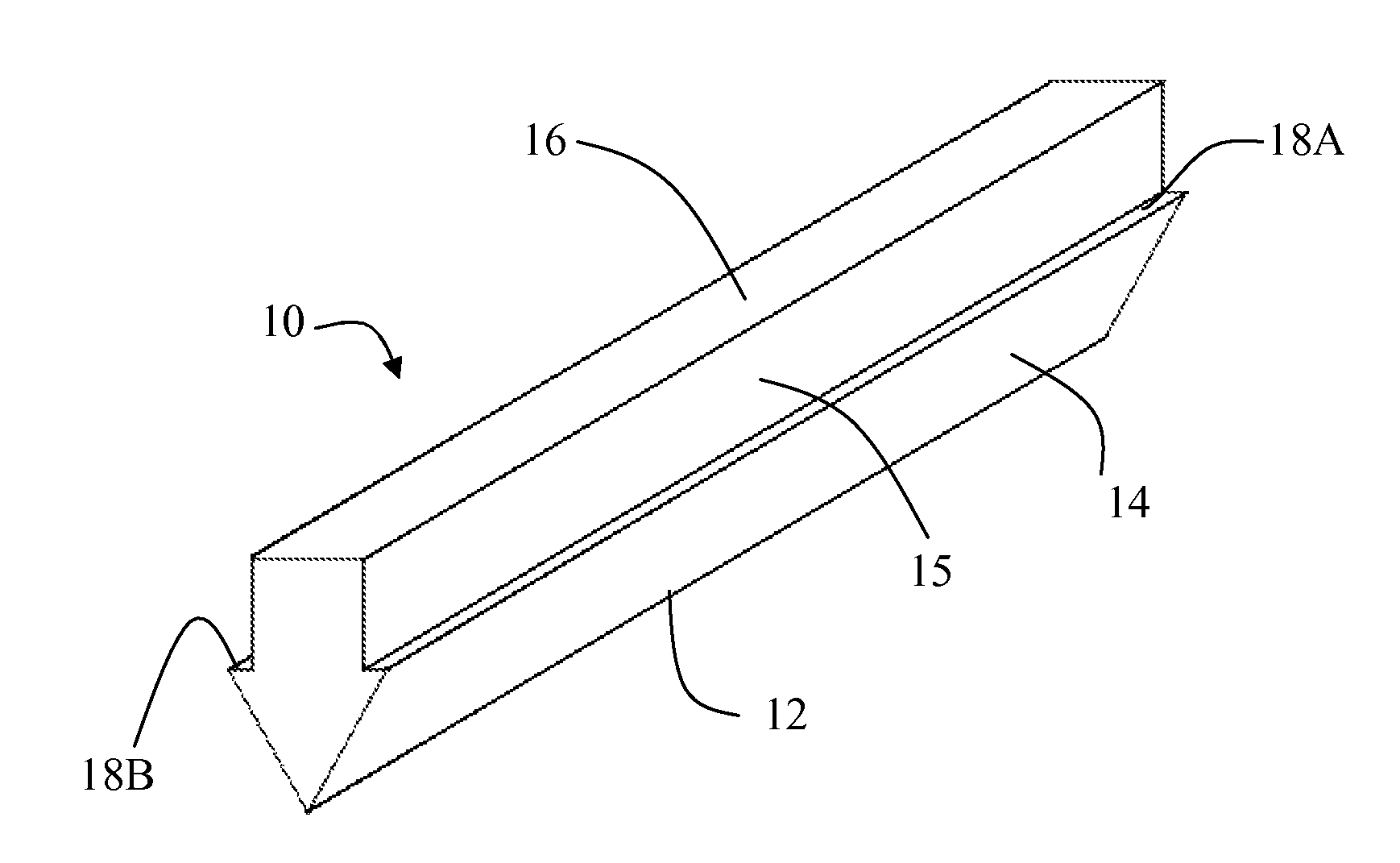
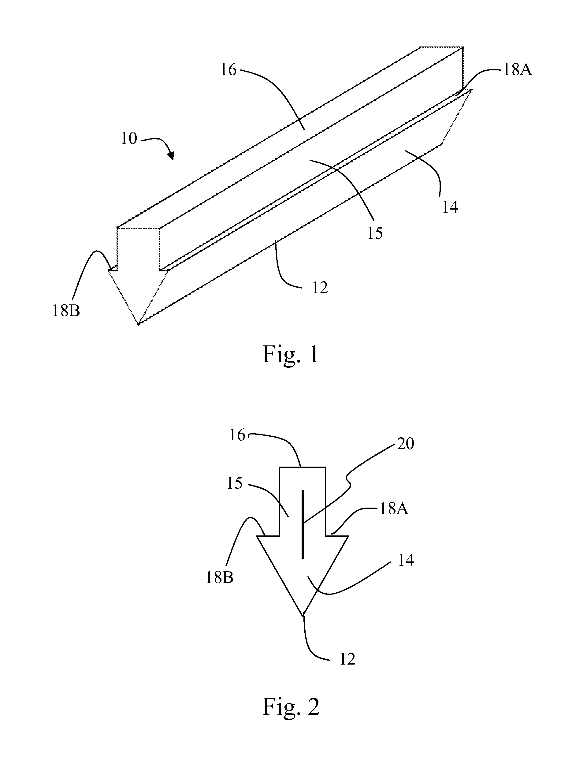
[0033]FIG. 1 shows a transponder 10 according to one embodiment of the invention. The transponder 10 is elongated in one direction and comprises a wedge-shaped first edge 12 on a longitudinal side thereof, the first edge 12 being adapted to penetrate to wood foremost. An elongated wedge-shaped first portion 14 extends from the first edge 12, serving to displace wood while the first edge 12 penetrates into the wood. The transponder further comprises a second portion 15, which extends from the broadest point of the wedge-shaped first portion 14 away from the first edge 12 and forms the second edge 16 of the transponder.

[0034]According to the embodiment shown in FIG. 1, the wedge-shaped first portion 14 has a maximum width in the lateral direction, which is greater than the maximum width of the second portion 15. In other words, there are formed two shoulders 18A, 18B extending in the lateral direction of the transponder at the region between the wedge-shaped first portion 14 and the s...


PUM

PropertyMeasurementUnit
angleaaaaaaaaaa
angleaaaaaaaaaa
opening angleaaaaaaaaaa

Abstract

The invention concerns a transponder (10), kit and method for marking wood material, such as logs. The transponder comprises a rigid casing adapted to be inserted into the wood material by means of impact, the casing comprising a wedge-shaped first edge (12) adapted to penetrate into the wood material due to said impact, and a second edge (16) opposite to the first edge, the first and second edges (12, 16) defining an insertion direction of the transponder, and radio-frequency trans-ponding means (20) covered by the casing. According to the invention, the casing is elongated in a direction perpendicular to the insertion direction. The transponder is easily applicable into a log and stays well within the log.

Description

FIELD OF THE INVENTION[0001]The invention relates to a special designed radio-frequency transponder and a method of applying the transponder into wood material, in particular into a log. In addition the invention relates to an application kit and a log comprising such transponder. The transponder of the present kind comprises a casing insertable into wood material, and radio-frequency transponding means covered by the casing.BACKGROUND OF THE INVENTION[0002]Radio-frequency identification (RFID)-based tracing is becoming increasingly common in many fields of trade and industry. Although many industrial sectors have utilized tracing systems, covering the product chain from the supplies of raw materials to the final products in the market, the forestry and wood sector is still in the beginning of this process partly due to a complicated supply chain structure. The nature of logging operation itself, logistics of the forest industry, environmental factors, needs of the user of the logs ...

Claims


Application Information

Patent Timeline
Patent Type & Authority Patents(United States)
IPC IPC(8): G06K19/06G06K7/08
CPCA01G23/099G06K19/04G06K19/07749Y10T29/49826G06K2017/0045A01G23/00
Inventor HAKLI, JANNEJAAKKOLA, KAARLENUMMILA, KAJSAARI, JUHA-MATTIAXELSSON, BOKOLPPO, KARI
Owner TEKNOLOGIAN TUTKIMUSKESKUS VTT
Why Eureka
Try Eureka