
Shear mode pressure-activated driver for magnetic resonance elastography

a magnetic resonance elastography and driver technology, applied in the field of magnetic resonance imaging (“ mri”) systems and methods, can solve the problems of mode conversion producing complex wave patterns, undesirable image artifacts, and limited forces

Active Publication Date: 2013-08-13
MAYO FOUND FOR MEDICAL EDUCATION & RES
View PDF16 Cites 12 Cited by
  • Summary
  • Abstract
  • Description
  • Claims
  • Application Information

AI Technical Summary

Benefits of technology

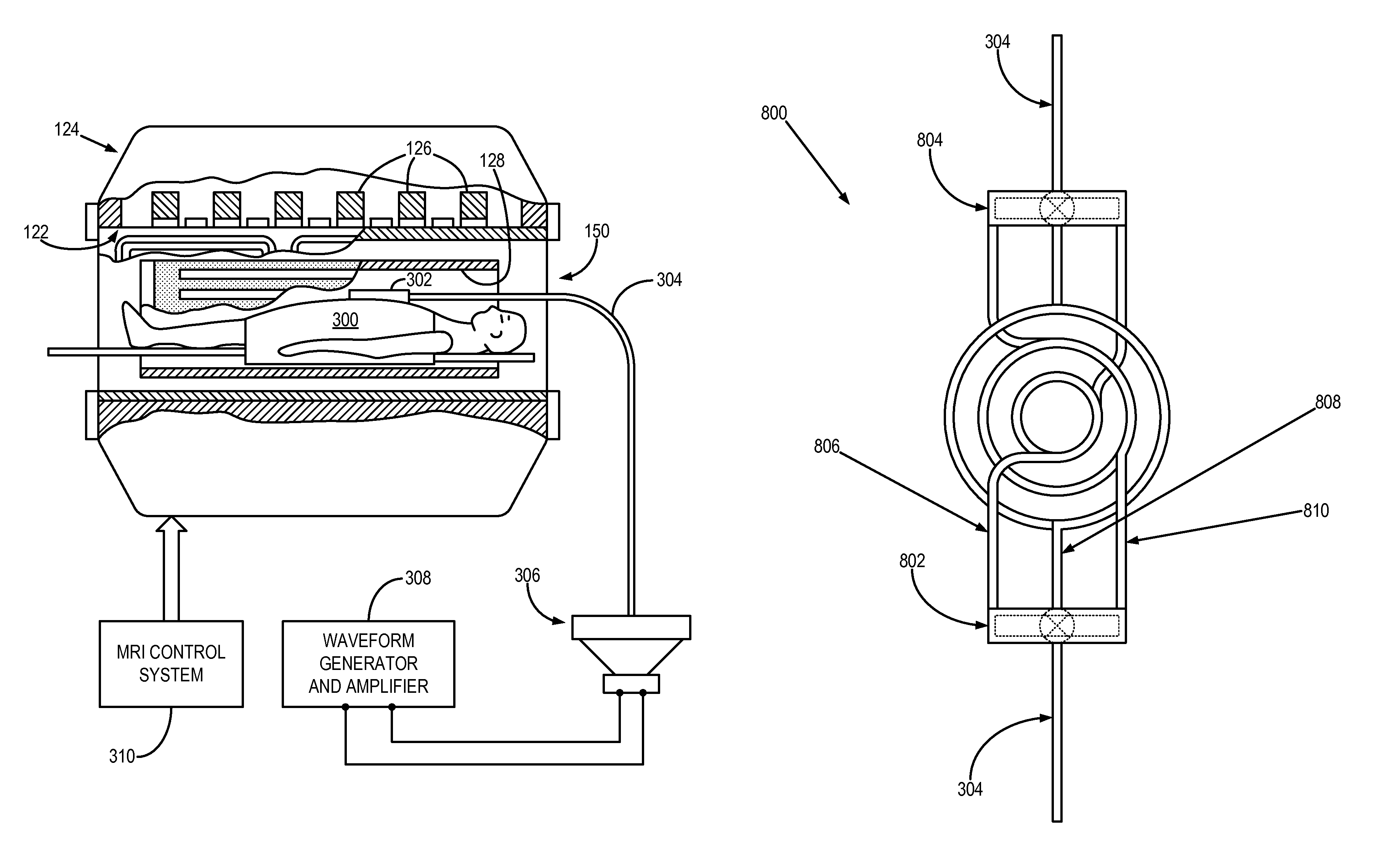
The present invention is a device that can produce shear waves in a person's body without interfering with the magnetic resonance imaging system. It includes a pneumatic driver located outside the MRI system, a pressure-activated driver positioned on the person, and a tube that connects the pneumatic driver to the person. The pneumatic driver creates pressure waves in the tube, which causes the pressure-activated driver to vibrate, applying a shear force to the person during the MRI examination. The technical effect of this invention is to enable a non-invasive and safe method for producing shear waves in a person's body, which can help diagnose and treat certain medical conditions.

Problems solved by technology

In addition, the current flowing in the driver coil produces a magnetic field that can alter the magnetic fields during the magnetic resonance pulse sequence resulting in undesirable image artifacts.
Such drivers do not produce troublesome disturbances in the scanner magnetic fields when operated, but they are limited in the forces they can produce, particularly at larger displacements.
Mode conversion produces complex wave patterns due to the fact that shear waves are generated at tissue interfaces whose geometry is often complex and multilayered.
Additionally, these tissue interfaces serve as multiple sources for shear wave production, resulting in constructive and destructive interference patterns that are difficult to model and separate.
Additionally, longitudinal waves introduce bulk motion into the subject, which produces phase errors that affect the estimation of the shear wavelength and, hence, stiffness estimates.

Method used


Image

  • Shear mode pressure-activated driver for magnetic resonance elastography
  • Shear mode pressure-activated driver for magnetic resonance elastography
  • Shear mode pressure-activated driver for magnetic resonance elastography

Examples


Embodiment Construction

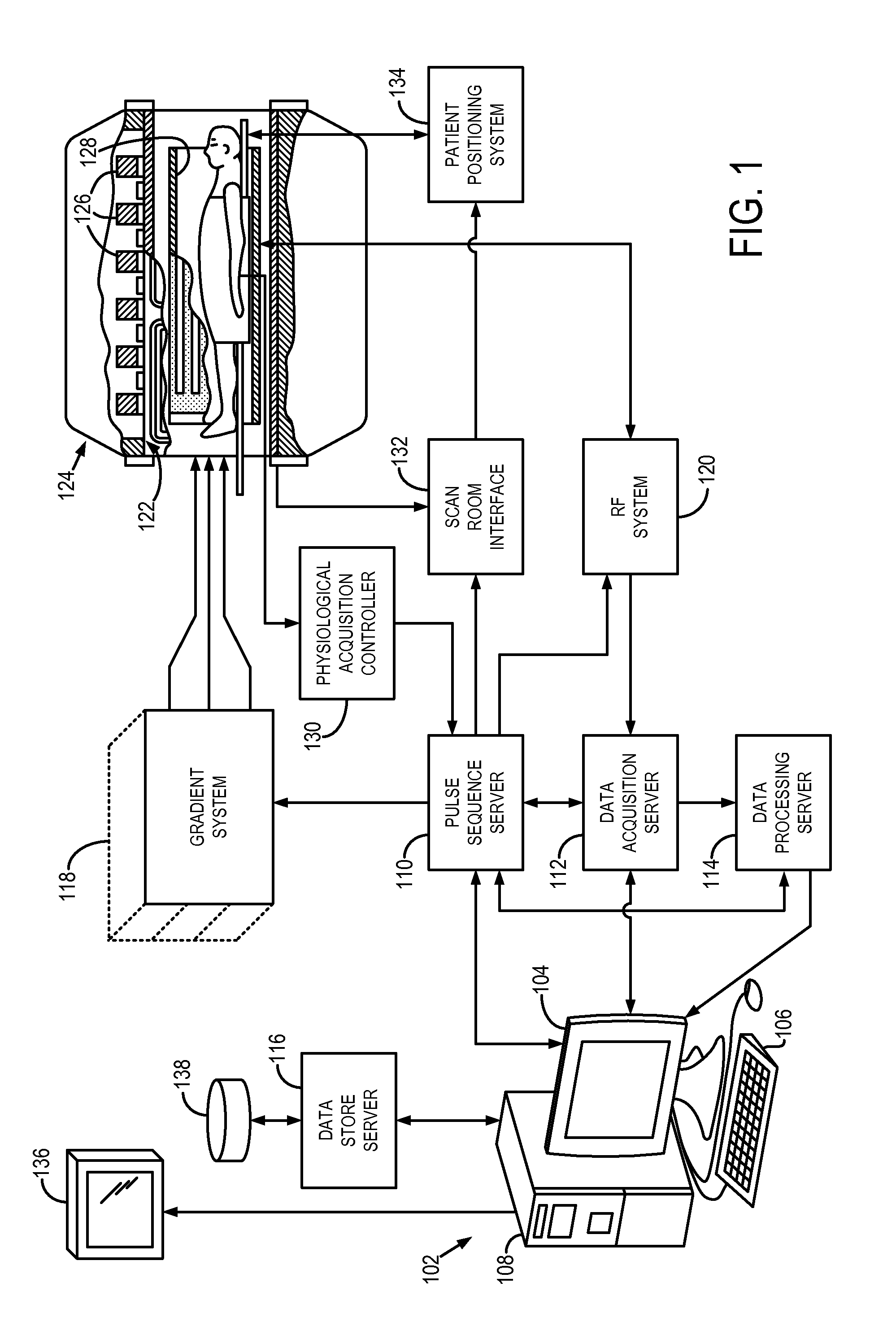
[0030]Referring particularly to FIG. 1, the preferred embodiment of the invention is employed in a magnetic resonance imaging (“MRI”) system 100. The MRI system 100 includes a workstation 102 having a display 104 and a keyboard 106. The workstation 102 includes a processor 108, such as a commercially available programmable machine running a commercially available operating system. The workstation 102 provides the operator interface that enables scan prescriptions to be entered into the MRI system 100. The workstation 102 is coupled to four servers: a pulse sequence server 110; a data acquisition server 112; a data processing server 114, and a data store server 116. The workstation 102 and each server 110, 112, 114 and 116 are connected to communicate with each other.

[0031]The pulse sequence server 110 functions in response to instructions downloaded from the workstation 102 to operate a gradient system 118 and a radiofrequency (“RF”) system 120. Gradient waveforms necessary to perfo...


PUM


Abstract

A magnetic resonance elastography (“MRE”) driver that can produce shear waves in a subject without relying on mode conversion of longitudinal waves is disclosed. More specifically, the MRE driver includes a pneumatic driver located remotely from a magnetic resonance imaging (“MRI”) system which is operable in response to an applied electrical current to oscillate, a pressure-activated driver that is positioned on a subject in the MRI system, and a tube that is in fluid communication, at one end, with the pneumatic driver. The pressure-activated driver includes a base plate and a driver plate having a region between them that receives the tube. Oscillations of the pneumatic driver produce a pressure wave in the tube that causes the driver plate to vibrate. The driver plate rests against the subject of interest to apply a corresponding shear oscillatory force to the subject during the MRE examination.

Description

CROSS-REFERENCE TO RELATED APPLICATIONS[0001]This application claims the benefit of U.S. Provisional Patent Application Ser. No. 61 / 229,776, filed on Jul. 30, 2009, and entitled “Shear Mode Pressure-Activated Driver for Magnetic Resonance Elastography.”STATEMENT REGARDING FEDERALLY SPONSORED RESEARCH[0002]This invention was made with government support under EB001981 awarded by the National Institute of Biomedical Imaging and Bioengineering. The government has certain rights in the invention.FIELD OF THE INVENTION[0003]The field of the invention is magnetic resonance imaging (“MRI”) systems and methods. More particularly, the invention relates to drivers for use in magnetic resonance elastography (“MRE”).BACKGROUND OF THE INVENTION[0004]Magnetic resonance imaging (“MRI”) uses the nuclear magnetic resonance (“NMR”) phenomenon to produce images. When a substance such as human tissue is subjected to a uniform magnetic field (polarizing field B0), the individual magnetic moments of the ...

Claims


Application Information

Patent Timeline
Patent Type & Authority Patents(United States)
IPC IPC(8): G01R33/565
CPCG01R33/56358
Inventor EHMAN, ERIC CMCGEE, KIARAN PEHMAN, RICHARD L
Owner MAYO FOUND FOR MEDICAL EDUCATION & RES
Learn More