
Bypass filter apparatus and method

a filter apparatus and filter technology, applied in the direction of filtration separation, separation process, wellbore/well accessories, etc., can solve the problems of contaminating injection fluid, too large debris to travel through the check valve, and affecting the flow rate of the injection fluid

Active Publication Date: 2013-08-06
SCHLUMBERGER TECH CORP
View PDF9 Cites 9 Cited by
  • Summary
  • Abstract
  • Description
  • Claims
  • Application Information

AI Technical Summary

Benefits of technology

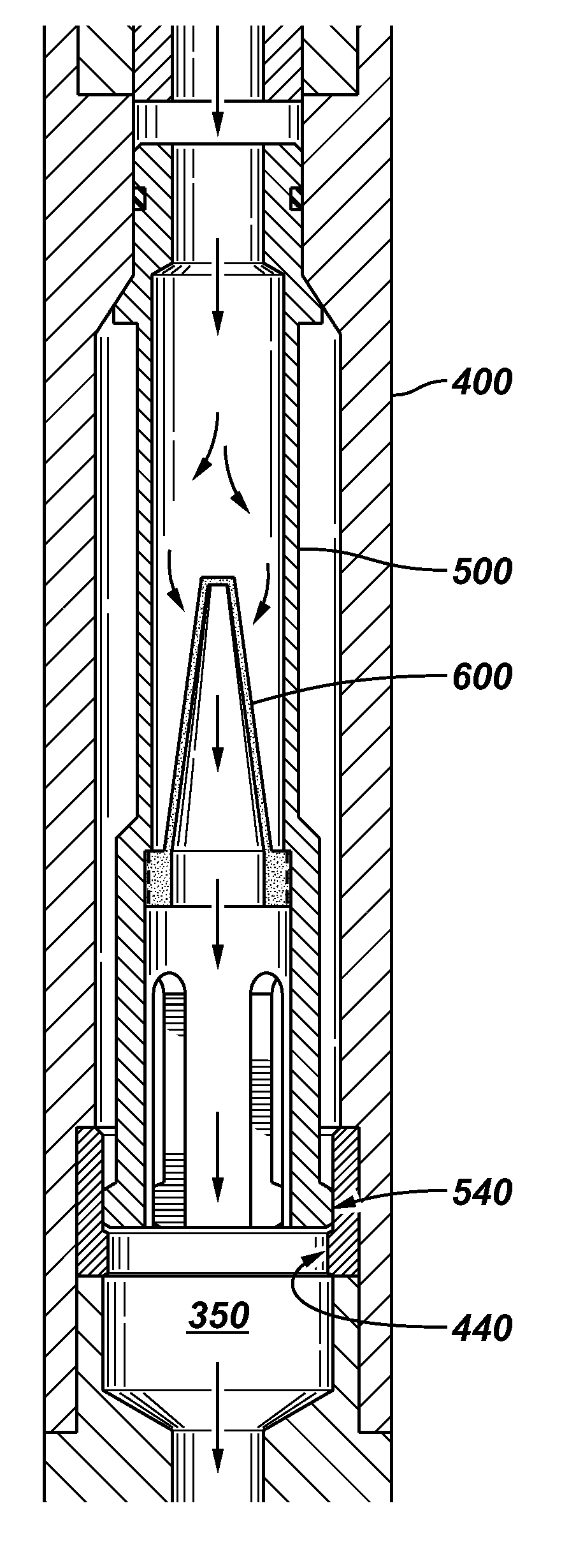
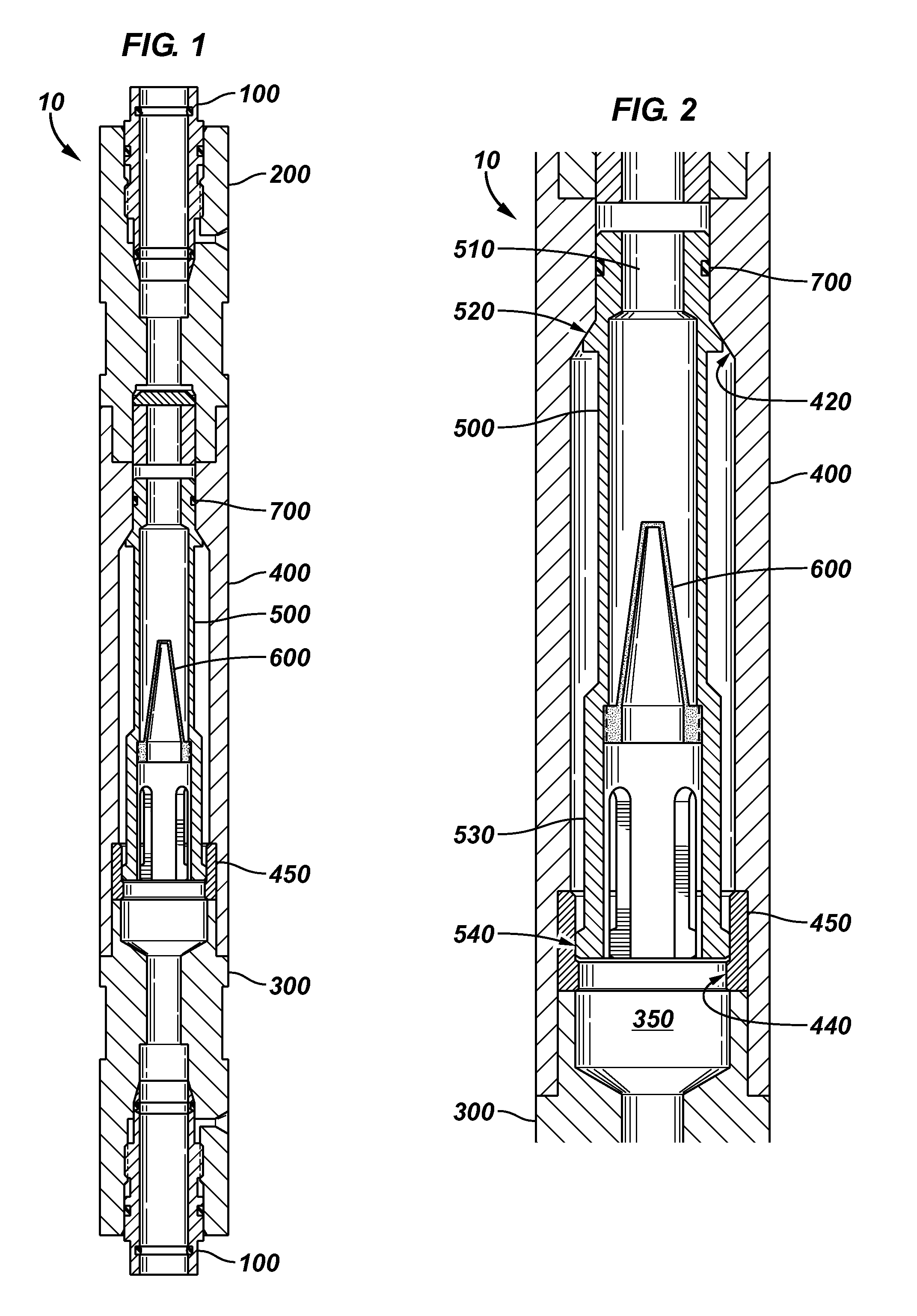
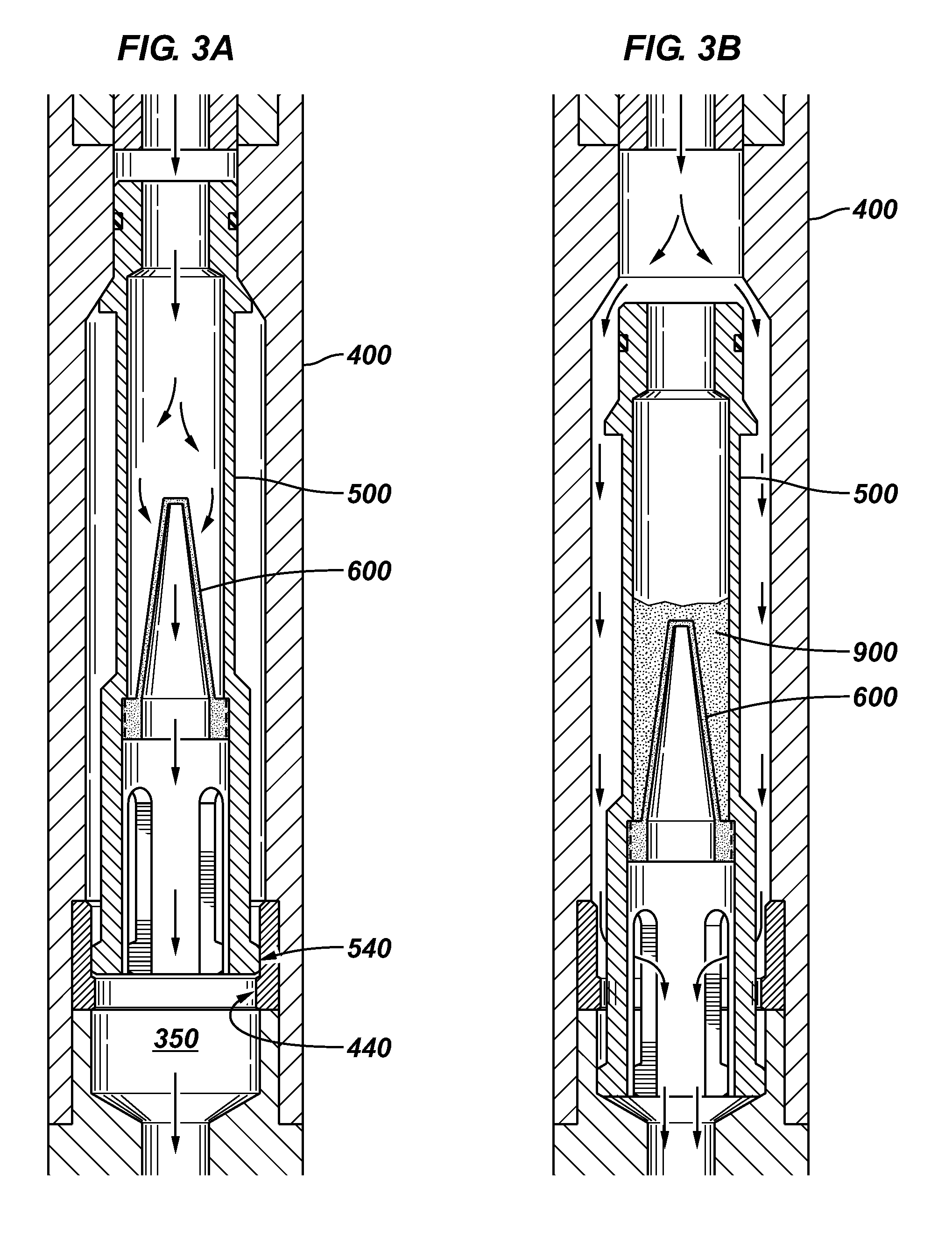
[0011]In accordance with another embodiment of the invention, a method to prevent chemical injection process failures may also be provided. The method may comprise the steps of providing a filter sub prior to a check valve. The filter sub may include a filter and a bypass mechanism. Another step may be passing fluid through the filter. In addition, the steps may also include containing at least some debris on a side of the filter such that the debris is prevented from reaching the check valve. A further step may be actuating the bypass mechanism after the debris builds up to a level in which a resulting load applied to the bypass mechanism exceeds a lower limit.

Problems solved by technology

Often debris will be too large to travel through the check valves and may become lodged in the valve.
If the check valves are unable to close, the pressure and fluid in the production tubing will be able to communicate with the injection line, thereby contaminating the injection fluid and otherwise preventing effective chemical injection of a well.
However, an improperly functioning chemical injection system may result in the removal of the completion.
In most cases debris related failures in chemical injection systems occur almost immediately after installation.
As injection begins the debris is quickly circulated downhole to the check valves, resulting in immediate initial failures.
The contamination level present in the treating chemicals of a chemical injection process is generally very low.
As such, if the valves are not damaged due to start up debris, the probability of future debris related failures is relatively low.

Method used


Image

  • Bypass filter apparatus and method
  • Bypass filter apparatus and method
  • Bypass filter apparatus and method

Examples


Embodiment Construction

[0019]In the following description, numerous details are set forth to provide an understanding of the present invention. However, it will be understood by those of ordinary skill in the art that the present invention may be practiced without these details and that numerous variations or modifications from the described embodiments may be possible. In the specification and appended claims: the terms “connect”, “connection”, “connected”, “in connection with”, “connecting”, “couple”, “coupled”, “coupled with”, and “coupling” are used to mean “in direct connection with” or “in connection with via another element”; and the term “set” is used to mean “one element” or “more than one element”. As used herein, the terms “up” and ““down”, “upper” and “lower”, “upwardly” and downwardly”, “upstream” and “downstream”; “above” and “below”; and other like terms indicating relative positions above or below a given point or element are used in this description to more clearly describe some embodimen...


PUM

PropertyMeasurementUnit
corrosionaaaaaaaaaa
pressureaaaaaaaaaa
shapeaaaaaaaaaa

Abstract

A filter sub apparatus comprising a housing configured to contain a filter and a bypass mechanism is provided. The bypass mechanism may be actuated upon debris buildup on the filter resulting in a load applied to the bypass mechanism rising above a predetermined lower level. A method to prevent chemical injection process failures may also be provided. The method may comprise the steps of providing a filter sub prior to a check valve. The filter sub may include a filter and a bypass mechanism. Another step may be passing fluid through the filter. In addition, the steps may also include containing at least some debris on a side of the filter such that the debris is prevented from reaching the check valve. A further step may be actuating the bypass mechanism after the debris builds up to a level in which a resulting load applied to the bypass mechanism exceeds a lower limit.

Description

RELATED APPLICATIONS[0001]This application claims the benefit of U.S. Provisional Application No. 61 / 045,139, filed Apr. 15, 2008, the contents of which are herein incorporated by reference.BACKGROUND[0002]1. Field of the Invention[0003]Embodiments of the present invention generally relate to inline filter devices used for filtering flowing fluid and more particularly to clog tolerant inline filter devices with a bypass feature such as may be used in a chemical injection system.[0004]2. Description of the Related Art[0005]The following descriptions and examples are not admitted to be prior art by virtue of their inclusion in this section.[0006]In typical wellbore operations, conventional chemical injection systems deploy selected chemicals in oil and gas wells for the purposes of controlling tubing corrosion, paraffin buildup, hydrate plugging, etc. Down-hole injection systems are typically comprised of a fluid reservoir, a surface pumping system, plumbing to the wellhead or sub-sea...

Claims


Application Information

Patent Timeline
Patent Type & Authority Patents(United States)
IPC IPC(8): C02F1/00
CPCB01D35/02B01D35/147B01D2201/02
Inventor HIMMEL, DAVID
Owner SCHLUMBERGER TECH CORP
Learn More