
Internal combustion engines

a combustion engine and internal combustion technology, applied in the direction of machines/engines, liquid fuel feeders, oscillatory slide valves, etc., can solve the problems of incomplete combustion, poor sealing of the rotor tips, and soon apparent problems, so as to minimize the loss of engine volume and internal out-of-balance components, reduce piston friction and cylinder wear, and minimize piston asymmetry

Active Publication Date: 2013-08-06
COX POWERTRAIN LTD
View PDF18 Cites 14 Cited by
  • Summary
  • Abstract
  • Description
  • Claims
  • Application Information

AI Technical Summary

Benefits of technology

The engine achieves superior performance to 4-cylinder 4-stroke engines with reduced height, lower mass, and improved installation suitability, featuring reduced friction, vibration, and enhanced fuel efficiency, making it suitable for hybrid powertrains and compact applications.

Problems solved by technology

By the end of the decade almost every major engine producer had bought licences from the Wankel Institute to produce rotary engines, but problems soon became apparent.
The first, poor sealing of the rotor tips, was eventually overcome, although only after many product recalls and warranty claims had brought pioneering manufacturers near to bankruptcy.
This leads to incomplete combustion due to the large area / volume ratio and inefficient shape.
With emissions as important today as fuel consumption, the inefficient combustion of the Wankel makes it hard to see it play any significant role in the future except in applications where the user is able to tolerate these deficiencies in exchange for its small size and smoothness.
However, this potential has been compromised by excessive inlet and exhaust period overlap and the fact that piston-opposed 2-strokes have not traditionally had optimum asymmetry to achieve the most efficient combustion.
Another contributor to the emissions produced and overall inefficiency of a conventional engine is that brought about by piston side thrust caused by connecting rod / crankshaft geometry, while frictional losses due to combustion forces acting directly on the big-end and main bearings are significant.
Improvements in all of these areas can only be beneficial.

Method used


Image

  • Internal combustion engines
  • Internal combustion engines
  • Internal combustion engines

Examples


Embodiment Construction

[0044]The following is a description of the preferred embodiment, but many variations are possible within the scope of the invention.

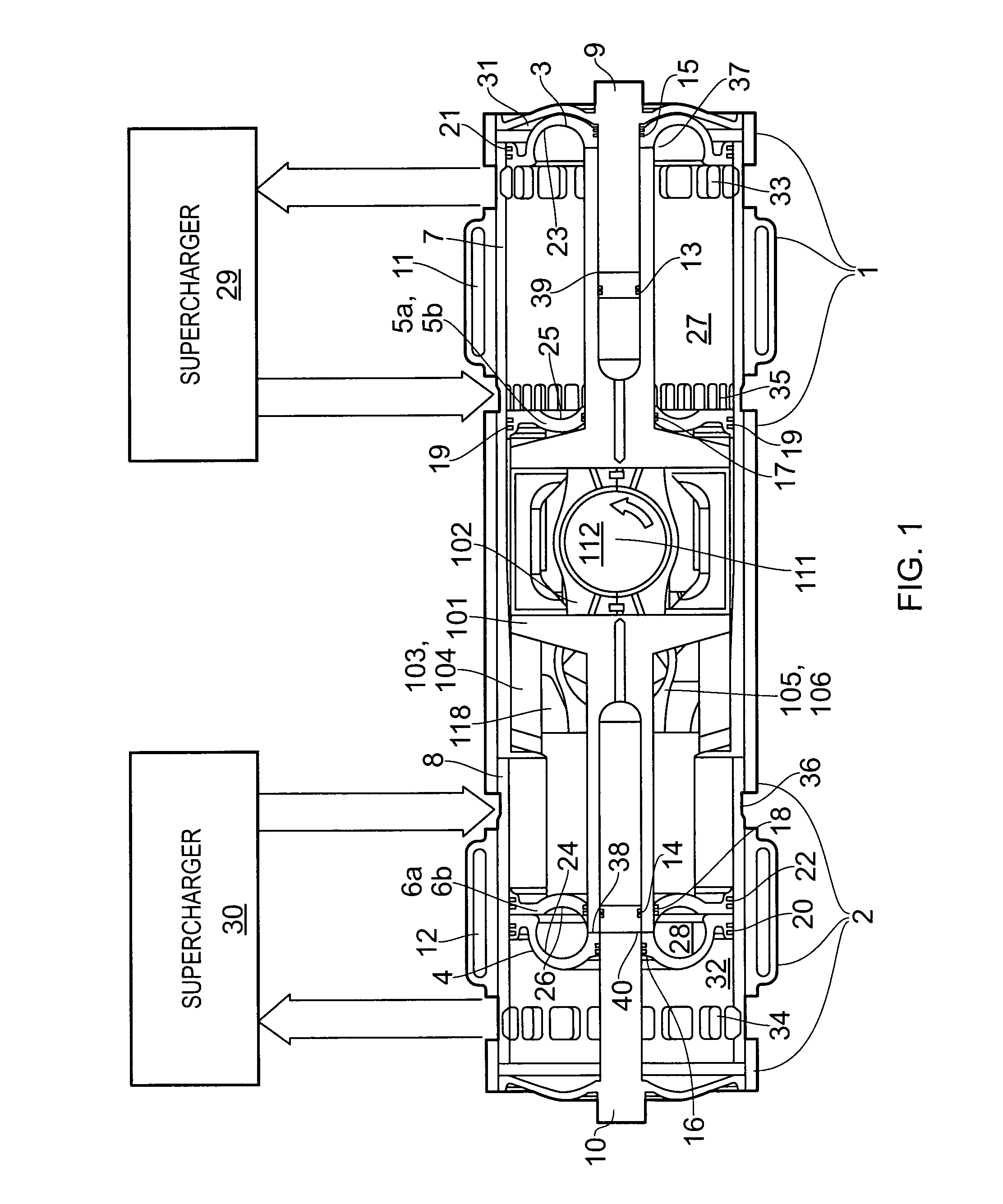
[0045]As illustrated in FIGS. 1 and 2, the engine configuration of the present invention comprises a right cylinder 7, a left cylinder 8 and a single central crankshaft 112 located between the cylinders (for clarity, most of the supporting structure of the engine, apart from 1 and 2 has been omitted from FIGS. 1 and 2).

[0046]The right cylinder 7 has an outer piston (PRO) 3 and an inner piston (PRO) 5 with combustion faces 23 and 25 respectively, the two pistons forming a combustion chamber 27 between them. The left cylinder 8 similarly has an outer piston 4 (PLO) and an inner piston (PLI) 6, with combustion faces 24 and 26 and combustion chamber 28. The two outer pistons 3 and 4 are rigidly connected together by the scotch yoke 101. The two upper, inner piston halves 5a and 6a are rigidly connected together by the upper scotch yoke 103 and the two lowe...


PUM


Abstract

The invention provides a 2-stroke internal combustion engine comprising two opposed cylinders, each cylinder housing two opposed pistons and having at least one exhaust port and at least one intake port, and a crankshaft having asymmetrically arranged journals and scotch-yoke mechanisms for driving the journals from the pistons. The pistons in each cylinder operate to open its exhaust port or ports before its intake port or ports and to close its exhaust port or ports before its intake port or ports.

Description

CROSS-REFERENCE TO RELATED APPLICATIONS[0001]This application claims priority to International Application No. PCT / GB2008 / 001798, filed on May 28, 2008, which claims priority to Great Britain Patent Application No. 0710852.5, filed Jun. 6, 2007, each of which is incorporated by reference in its entirety.FIELD OF THE INVENTION[0002]This invention relates to internal combustion engines. More particularly it relates to internal combustion engines with a piston-opposed, cylinder-opposed (“POCO”) configuration.BACKGROUND[0003]The internal combustion engine has undergone very little change since the end of the Second World War and it is arguable that the piston engine in almost universal use today has more in common with design practice at the outbreak of WW2 than the developments that took place during it.[0004]With the war over, the requirement was for something which was cheap and simple to produce, something that did not require especially advanced machining techniques or exotic mater...

Claims


Application Information

Patent Timeline
Patent Type & Authority Patents(United States)
IPC IPC(8): F01B7/12F02B25/08F02B75/28
CPCF01B1/08F01B7/04F01B9/023F02B25/08F02B75/24F02B75/28F01B7/10Y02T10/125F02B2075/025F02B2075/1808F02B2275/40F02F1/22F02F3/0015Y02T10/12F02B75/32
Inventor COX, DAVID
Owner COX POWERTRAIN LTD
Learn More