Magneto-resistive effect element having spacer layer containing gallium oxide, partially oxidized copper

a technology of magnetoresistive effect and spacer layer, which is applied in the field of magnetoresistive effect element, can solve the problems of difficult to place anti-ferromagnetic layer within the read gap, technology is not preferable from the view point of reliability, and difficult to maintain a balance between

Active Publication Date: 2013-07-30
TDK CORPARATION
View PDF15 Cites 2 Cited by
  • Summary
  • Abstract
  • Description
  • Claims
  • Application Information

AI Technical Summary

Benefits of technology

[0010]Compared to a conventional spacer layer formed of a metal layer such as copper or the like, the spacer layer including the main spacer layer composed of gallium oxide as a main component can realize a large MR ratio. Gallium oxide normally exists in an amorphous state when gallium oxide is in a thin film state; however, there are advantages in that wide band gap can be maintained even in the amorphous state and in that no lattice matching (matching of lattice constants of two adjacent materials) between the spacer layer and an adjacent magnetic layer is required.
[0011]On the other hand, as described above, a magnetic layer adjacent to the spacer layer is normally composed of Co, Ni, Fe or the like as a primary component. Accordingly, when these elements are positioned in a manner of contacting gallium oxide, the magnetic layer is oxidized due to an oxidization action of oxygen contained in gallium oxide, and therefore there is a possibility for the MR ratio to decrease. Specifically, gallium oxide oxidizes elements configuring the first magnetic layer by oxygen contained therein diffusing, the polarizability is decreased, and therefore there is a possibility to decrease the MR ratio.
[0012]Accordingly, in the present invention, the spacer layer is provided with a bottom layer composed of partially oxidized copper as a primary component. Copper has an effect that prevents diffusion of oxygen contained in gallium oxide. Also, in oxidized copper compared to unoxidized copper, electron scattering is less likely to occur. By disposing such a bottom layer, the antioxidation effect of copper can be maintained, the electron scattering can be suppressed, and an MR ratio can be increased.

Problems solved by technology

However, when the read gap is reduced to approximately 20 nm, it is difficult to place an anti-ferromagnetic layer within the read gap.
However, because a sense current is concentrated to a conductive part so that a current density is increased, this technology is not preferable from the view point of reliability.
For these reasons, it is difficult to maintain a balance between two demands that are the antioxidant and the prevention of electron scattering.

Method used


Image

  • Magneto-resistive effect element having spacer layer containing gallium oxide, partially oxidized copper
  • Magneto-resistive effect element having spacer layer containing gallium oxide, partially oxidized copper
  • Magneto-resistive effect element having spacer layer containing gallium oxide, partially oxidized copper

Examples


first embodiment

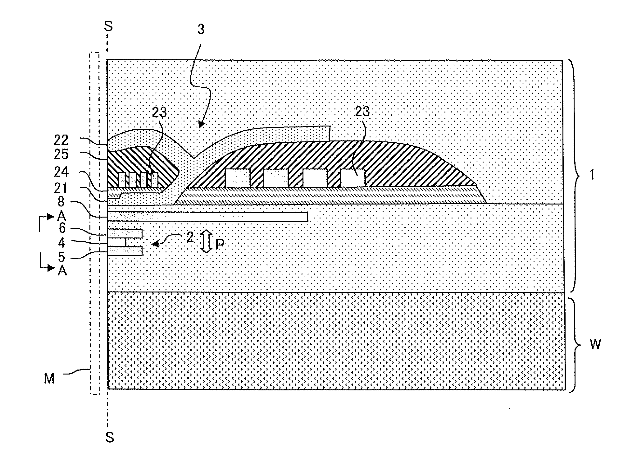
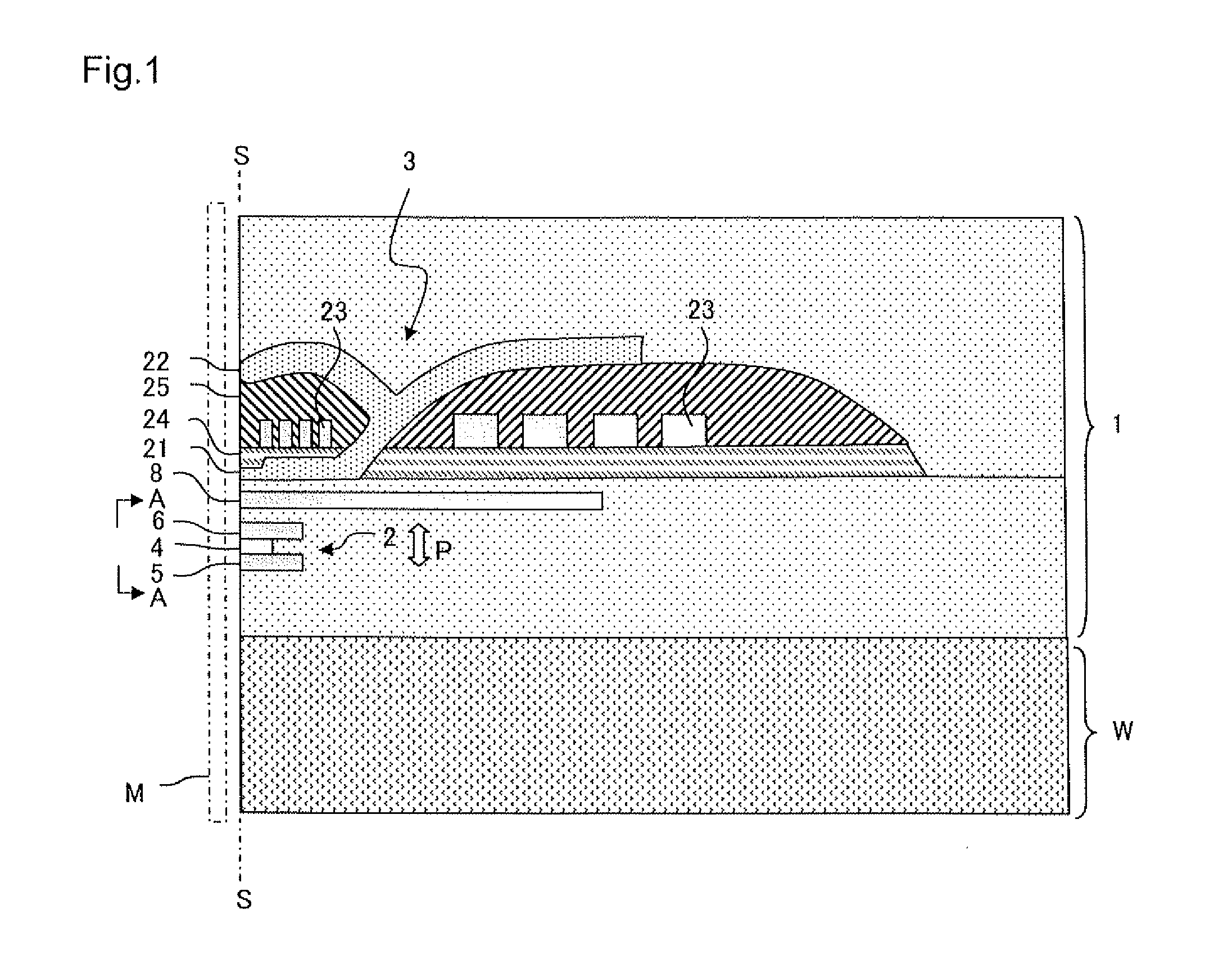
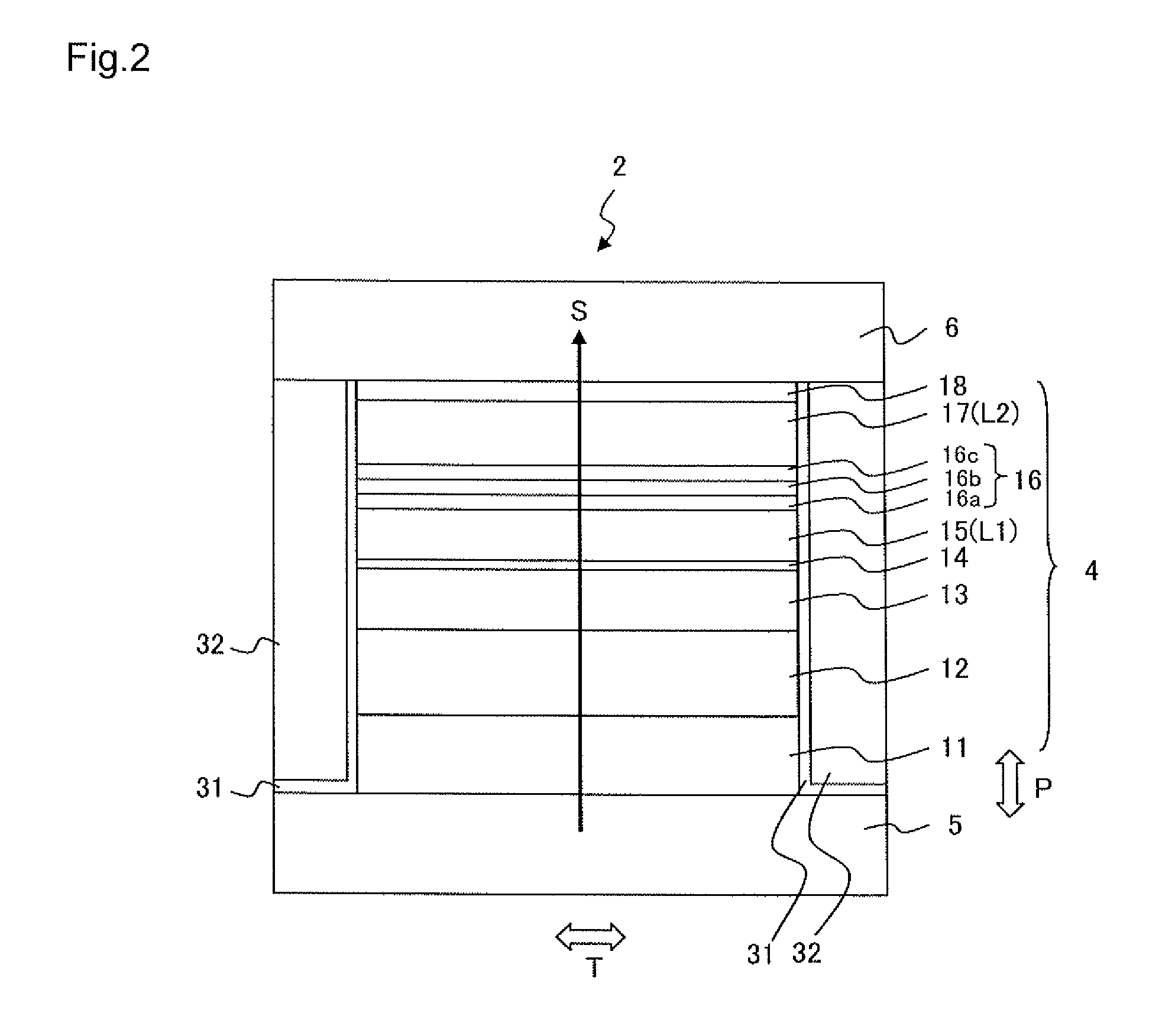
[0024]FIG. 1 illustrates a main part cross-sectional view of a thin film magnetic head 1 according to a first embodiment. The thin film magnetic head 1 is formed on a substrate W and includes a reproducing head 2 and a recording head 3. FIG. 2 is a side view of the reproducing head 2 as viewed from the A-A direction of FIG. 1 and illustrates a layer configuration of the reproducing head 2 on the air bearing surface S. The air bearing surface S is a surface of the thin film magnetic head 1 that faces a recording medium M. First, a description is given regarding a configuration of the reproducing head 2 with reference to FIG. 2.

[0025]The reproducing head 2 includes a spin valve type MR element 4, upper and lower shield layers 6 and 5 disposed in a manner of sandwiching the MR element 4 in a film surface orthogonal direction (lamination direction) P, and bias magnetic field application layers 32 disposed on both sides in the track width direction T (sheet surface orthogonal direction i...

second embodiment

[0043]A thin film magnetic head 1 of the present embodiment is the same as the first embodiment illustrated in FIG. 1 with the exception of the configuration of the reproducing head 2. FIG. 3 and Table 2 illustrate a layer configuration of such an MR element. A reproducing head 102 includes an MR element 104 in which a large number of layers are laminated in the same manner as the first embodiment, and upper and lower shield layers 106 and 105 that are disposed in a manner of sandwiching the MR element 104 in the film surface orthogonal direction P (lamination direction). The upper and lower shield layers 106 and 105 are also used as electrodes for a sense current S so that a sense current S flows in the film surface orthogonal direction P of the MR element 104.

[0044]In the present embodiment, a first magnetic layer L1 and a second magnetic layer L2 are both magnetization free layers 115 and 117 of which the respective magnetization directions change in response to an external magne...

example

[0059]An MR element with the layer configuration illustrated in Table 2 was formed above a substrate composed of Al2O3—TiC (ALTIC) by using a sputtering device. A nonmagnetic layer 116c was composed of Zn. After a film forming chamber pressure was depressurized to a vacuum atmosphere having 10−6 Pa or less, Ar gas was introduced into the film forming chamber and layers were formed under a sputtering pressure of approximately 0.1 Pa. A gallium oxide layer was formed by a radio frequency (RF) sputtering method, and other films were formed by a direct current (DC) magnetron sputtering method. The bottom layer was formed by forming a Cu film in a metal state and then partially oxidizing the Cu film by an oxygen plasma treatment (power: 30 W, Ar gas flowing rate: 10 mL / min, and oxygen gas flow rate: 20 mL / min). After the layers illustrated in Table 2 were formed, a heating (annealing) treatment was performed at 250° C. for three hours, and the MR element having a junction size of 0.2 μm×...


PUM

PropertyMeasurementUnit
mole fractionaaaaaaaaaa
thicknessaaaaaaaaaa
thicknessaaaaaaaaaa

Abstract

A magneto-resistive effect (MR) element includes first and second magnetic layers where a relative angle formed by magnetization directions changes in response to an external magnetic field and a spacer layer positioned between the first magnetic layer and the second magnetic layer. The first magnetic layer is positioned closer to a substrate above which the MR element is formed than the second magnetic layer. The spacer layer includes a main spacer layer that is composed of gallium oxide as a primary component and a bottom layer that is positioned between the main spacer layer and the first magnetic layer and that is composed of partially oxidized copper as a primary component.

Description

BACKGROUND OF THE INVENTION[0001]1. Field of the Invention[0002]The present invention relates to a magneto-resistive effect (MR) element and particularly to a configuration of a spacer layer.[0003]2. Description of the Related Art[0004]Reproducing heads with high sensitivity and high output are in demand in conjunction with condensing of high recording density in hard disk drives (HDD). As an example of this type of reproducing head, a spin valve head has been developed. A spin valve head includes a nonmagnetic metal layer and a pair of ferromagnetic layers positioned on both sides of the nonmagnetic metal layer in a manner of contacting the nonmagnetic metal layer. The magnetization direction of one of the ferromagnetic layers is pinned in one direction (hereinafter, this type of layer is referred to as a magnetization pinned layer), and the magnetization direction of the other freely rotates in response to an external magnetic field (hereinafter, this type of layer is referred to ...

Claims


Application Information

Patent Timeline
Patent Type & Authority Patents(United States)
IPC IPC(8): G11B5/39
CPCB82Y10/00B82Y25/00G11B5/3929Y10T428/1121G11B2005/3996
Inventor KOIKE, HAYATOCHOU, TSUTOMUTSUCHIYA, YOSHIHIROMATSUZAWA, HIRONOBU
Owner TDK CORPARATION
Why Eureka
Try Eureka