
Method and system for fiber-optic monitoring of spatially distributed components

a technology of fiber optics and components, applied in the direction of optical elements, instruments, heat measurement, etc., can solve the problems of inability to carry out frequent time, cumbersome monitoring and maintenance of ancillary elements of electric power distribution cables, and critical environment where cables are located, so as to increase the reliability of the monitoring system

Active Publication Date: 2013-07-16
PRYSMIAN SPA
View PDF9 Cites 6 Cited by
  • Summary
  • Abstract
  • Description
  • Claims
  • Application Information

AI Technical Summary

Benefits of technology

This patent describes a monitoring system that uses an additional optical branch to detect events like the breakage of a monitored component. This branch becomes non-reflective when the component breaks, allowing the system to detect these events and increase its reliability. The text also mentions the concept of "Fresnel reflection," which is based on the behavior of light in different media, and how this reflection occurs when light moves from a dense to a less dense medium. The technical effect of this patent is the improved reliability and accuracy of the monitoring system.

Problems solved by technology

The environment where the cables are located can be critical because recessed and / or dangerous, like in the case of HV networks.
Thus, the monitoring and the maintenance of the ancillary elements of an electric power distribution cable may be cumbersome, and cannot be carried out on a frequent time basis.
Even when the ancillary elements are not enclosed in protective boxes, the monitoring of their operating conditions can imply long inspection time and / or the interruption of the distribution of the electric power.
This is indeed strongly undesired because an electric power distribution line normally supplies a very large area and a substantial number of users who are never ready to accept a service interruption.

Method used


Image

  • Method and system for fiber-optic monitoring of spatially distributed components
  • Method and system for fiber-optic monitoring of spatially distributed components
  • Method and system for fiber-optic monitoring of spatially distributed components

Examples


Embodiment Construction

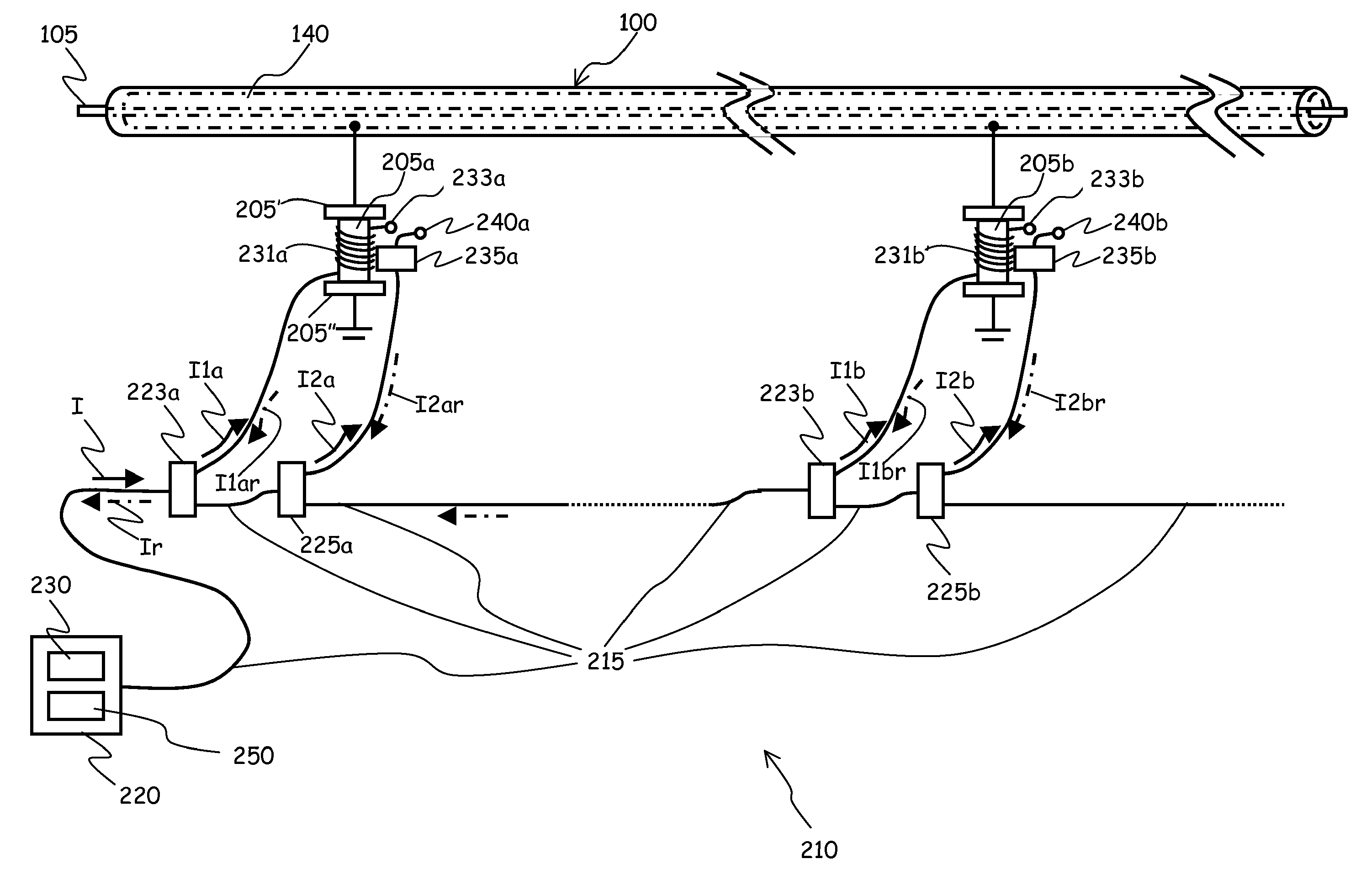
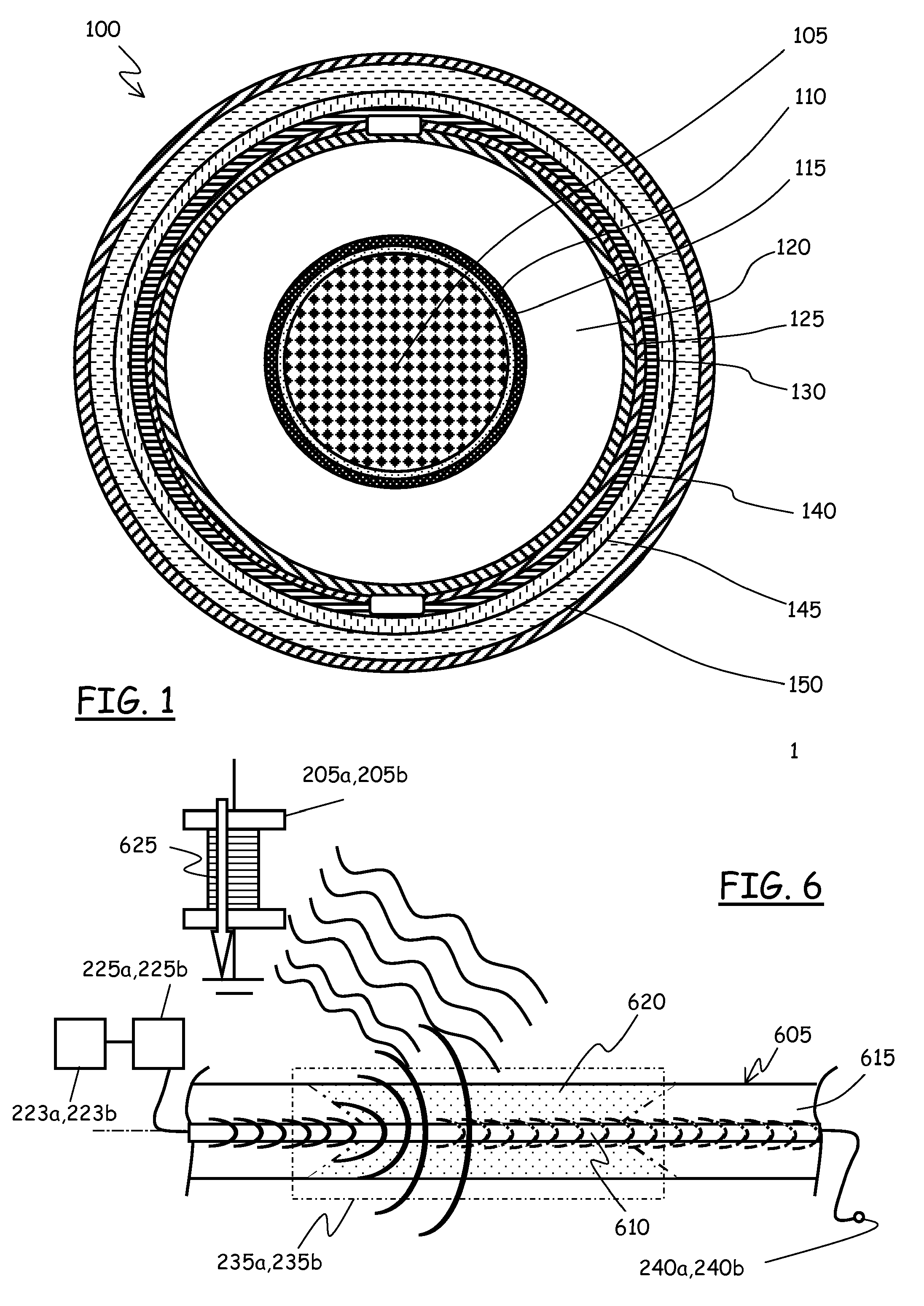
[0078]FIG. 1 shows, in cross section, a cable 100 for HV electric power distribution networks, particularly a single-core cable. The cable 100 comprises, starting from the center thereof and moving radially outwards, a central conductor 105, a binder 110, made of a semi-conductive tape, a conductor screen 115, made of a semi-conductive polymer, an insulation layer 120 made, for example, of cross-linked polyethylene (XLPE), an insulation screen 125, made of a semi-conductive polymer, a semi-conductive water barrier 130, made for example of a semi-conductive hygroscopic tape, a metallic sheath 140, made of a metal sheet, a jacket 145 of high-density polyethylene (HDPE), and finally a protective coating 150. The cable 100 can be used both in aerial applications or underground.

[0079]The metallic sheath 140 has primarily the function of making the electromagnetic field uniform around the conductor 105.

[0080]Phenomena like lightning, switch-on maneuvers of the electric power distribution ...


PUM

PropertyMeasurementUnit
voltagesaaaaaaaaaa
distanceaaaaaaaaaa
angleaaaaaaaaaa

Abstract

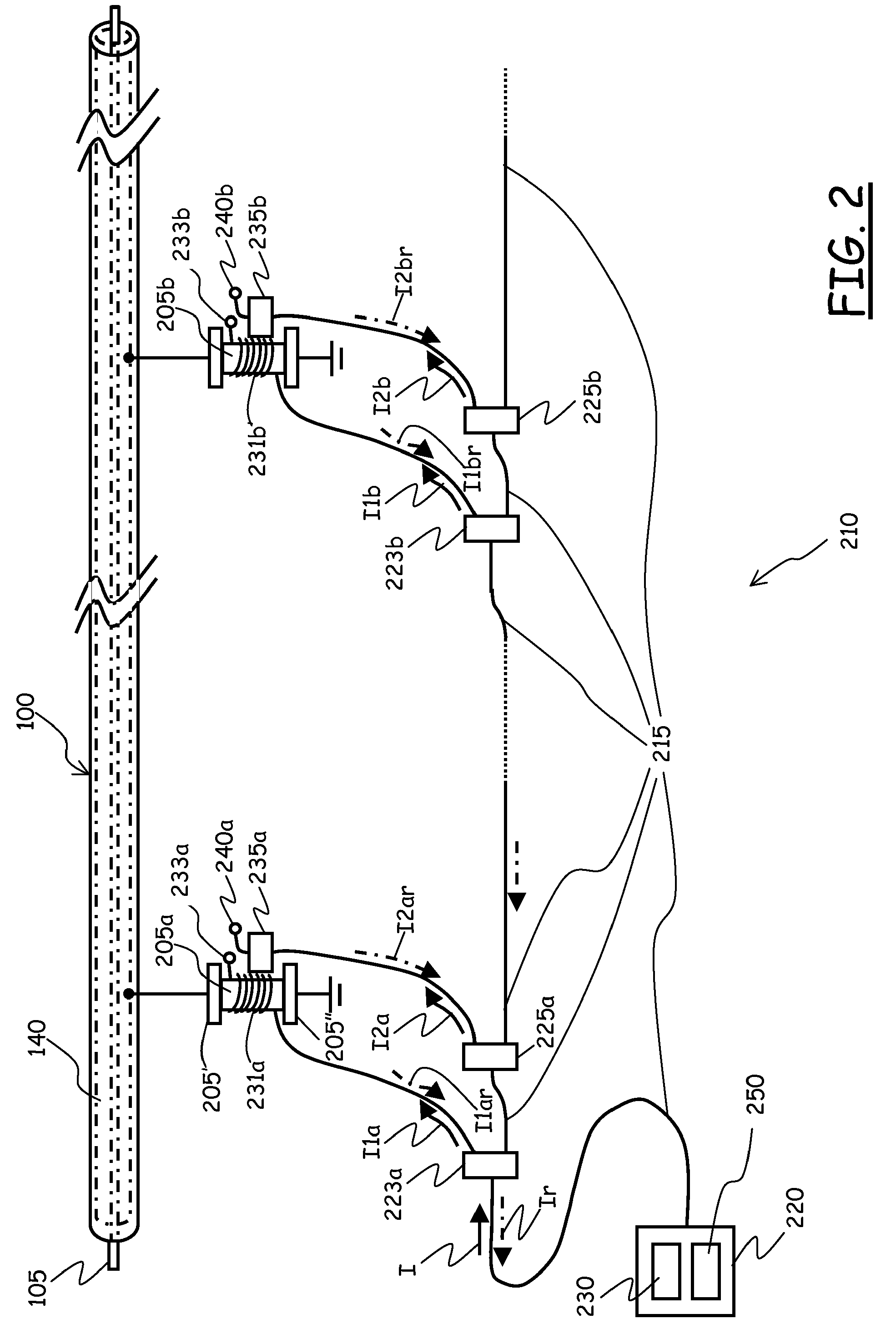
A system for monitoring a plurality of components distributed in different space locations, includes: at least one optical fiber path; an optical radiation source adapted to inject optical radiation into the at least one optical fiber path; at least one first and at least one second optical branches branching from the at least one optical fiber path and adapted to spill respective portions of the optical radiation, the first and second optical branches being adapted to be operatively associated with a respective component to be monitored. The first optical branch includes a first optical reflector and is adapted to reflect the spilled optical radiation portion unless the respective component at least partially breaks; the second optical branch includes at least one passive optical attenuator adapted to be operatively coupled to the respective component to be monitored, and having an attenuation capable of changing in response to a change in operating conditions of the respective monitored component when operatively coupled thereto, and a second optical reflector. An optical receiver is adapted to detect back-reflected optical radiation reflected by the first and second optical branches. The monitoring system is adapted to recognize a position of a component of the plurality of components based on a characteristic of the back-reflected optical radiation.

Description

CROSS REFERENCE TO RELATED APPLICATION[0001]This application is a national phase application based on PCT / EP2007 / 063002, filed Nov. 29, 2007, the content of which is incorporated herein by reference.BACKGROUND OF THE INVENTION[0002]1. Field of the Invention[0003]The present invention relates in general to methods and systems for monitoring the state of components distributed in a plurality of spatial locations, particularly, although not limitatively, electric power distribution system components. In particular, the present invention concerns the monitoring, in real time and by exploiting optical fibers, of the state and condition of components such as “ancillary” elements of electric power distribution networks, for example elements used for ensuring the system security.[0004]2. Description of Related Art[0005]Distribution systems of electric power comprise distribution networks, for example high voltage (HV) distribution networks.[0006]The term “high voltage” is related to voltage...

Claims


Application Information

Patent Timeline
Patent Type & Authority Patents(United States)
IPC IPC(8): G01N21/00G02B6/00G01R31/00H04B10/00
CPCG01K11/3206G01D5/35383G01D5/35367G01D5/3539G01D5/35377
Inventor GASPARI, ROBERTO
Owner PRYSMIAN SPA
Learn More