
Blank and database of prefabricated partial surfaces of dental prosthetics

a dental prosthetic and prefabricated technology, applied in dental prosthetics, medical simulation, tooth crowns, etc., can solve the problems of veneering to dental prosthetic items, no degree of freedom for customizing the remaining exterior surface, and malfunction information, so as to facilitate the design of dental prosthetic items

Active Publication Date: 2013-07-09
SIRONA DENTAL SYSTEMS
View PDF47 Cites 18 Cited by
  • Summary
  • Abstract
  • Description
  • Claims
  • Application Information

AI Technical Summary

Benefits of technology

[0028]In the method of the invention, it is accordingly possible to carve a large number of different dental prosthetic items from one type of blank having a specific terminal subsurface, which prosthetic items will, on the one hand, have designed subregions that are similar to said terminal subsurface and, on the other hand, show different external shapes in the region outside of said terminal subsurface. When manufacturing the blank, it is, unlike in the case of complete prefabrication, only necessary to pre-fabricate one particular terminal subsurface of esthetic significance, for example as regards shape, coloration, and translucency, so as to correspond to the planned dental prosthetic item. This simplifies the production process.
[0066]Advantageously, the 3D model is only available for adaptation outside the border line of the terminal subsurface for the purposes of designing the 3D model of the individual dental prosthetic item, whilst preferably a size-reducing adaptation in the marginal area of the terminal subsurface may be permissible. As opposed to finished teeth, this provides additional degrees of freedom for machining several different dental prosthetic items having the same prefabricated esthetic surface from one type of blank.

Problems solved by technology

This suffers from the drawback that the prefabricated teeth can only be fitted at the preparation border in the cervical region and there are thus no degrees of freedom for customizing the remaining exterior surface to the anatomical situation in the oral cavity of the patient.
In addition, it can be detrimental when the exterior surfaces of the prefabricated tooth in the region of the preparation border are only slightly oversize relative to the final shape of the prosthetic item to be produced.
Since only a small amount of material has to be removed in the cervical region, malfunction information may occur during the machining process even if the machining tool is not fractured but because the friction forces produced on the material to be machined are too low.
This suffers from the drawback that the attachment of the veneer to a dental prosthetic item while taking into consideration the planned translucency profile and coloration of the dental prosthetic item is time-consuming and requires great technical effort.
Consequently, it is not possible to provide the patient with a dental prosthetic item during a single session.
The drawback here is that a very large assortment of blanks must be available for the purpose of finding a blank which matches the tooth and has the same outer shape.
This suffers from the drawback that the individual premolds forming the complete prosthesis can only be adapted to each other at their adjacent surfaces, but not at their exterior surfaces.
Such partial crowns are suitable for replacing a partially damaged tooth, but not the entire tooth.
This suffers from the drawback that with this method all surfaces of the dental prosthetic item must be carved from the blank by milling, which means that the esthetically relevant surfaces must be subsequently veneered to comply with the esthetic requirements of a dental prosthesis.
The disadvantage here is that the esthetically relevant surfaces must, after machining, be subsequently reworked in order to satisfy the esthetic requirements of a dental prosthesis.

Method used


Image

  • Blank and database of prefabricated partial surfaces of dental prosthetics
  • Blank and database of prefabricated partial surfaces of dental prosthetics
  • Blank and database of prefabricated partial surfaces of dental prosthetics

Examples


Embodiment Construction

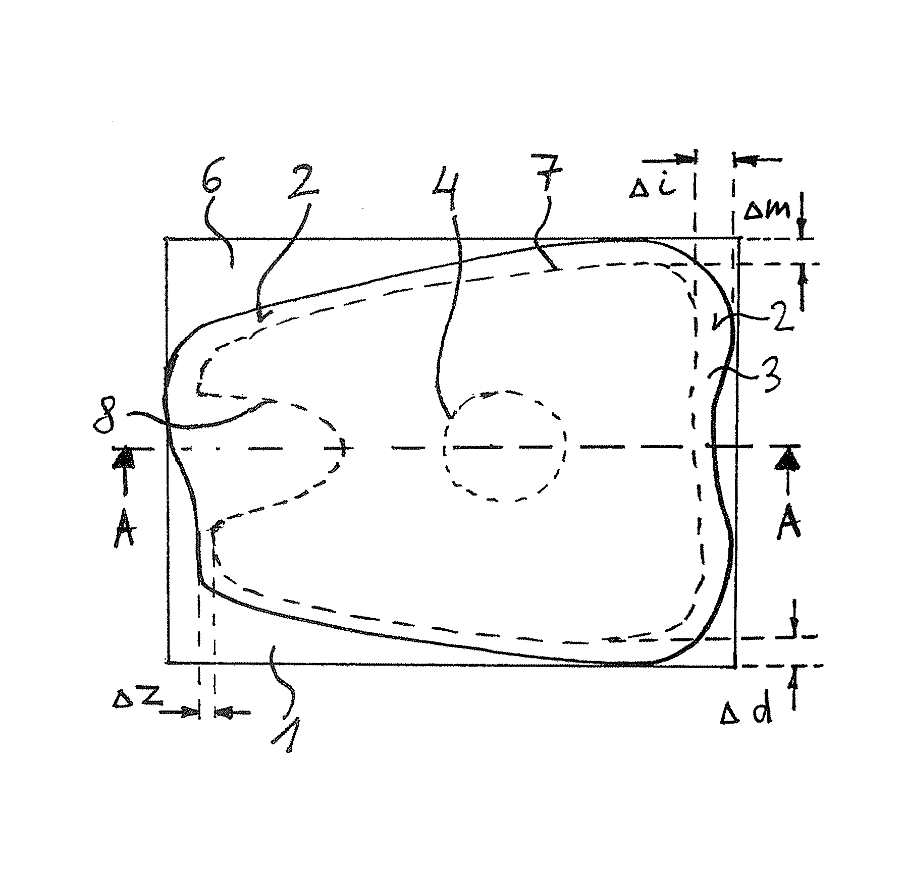
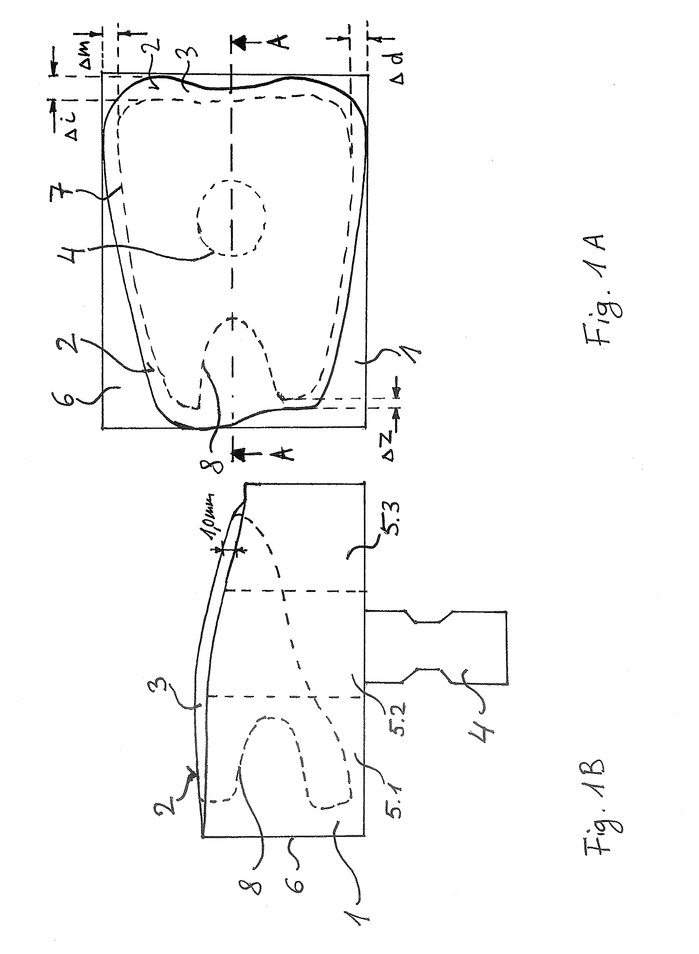
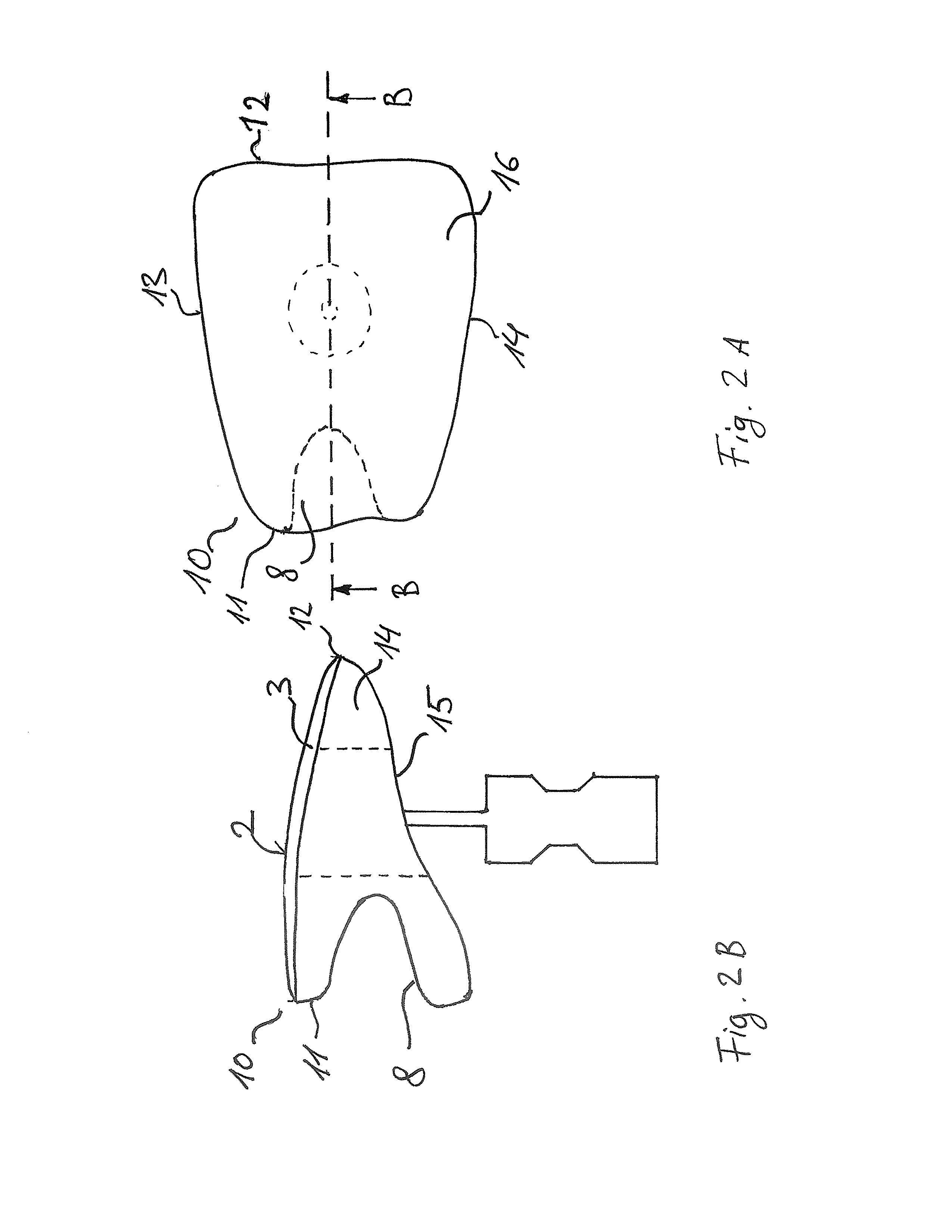
[0086]FIG. 1A is a top view of a blank 1 for the production of a dental prosthetic item for an incisor and FIG. 1B is a sectional view taken along the line A-A. The blank 1 has a prefabricated terminal subsurface 2, which is disposed on a translucent layer 3. The prefabricated terminal subsurface 2 corresponds in shape to a lower right-hand incisor having tooth number 41 according to the International Tooth Numbering System. The blank 1 comprises a holder 4 for fitting the blank 1 into machining equipment (not shown).

[0087]The prefabricated terminal subsurface 2 has the shape of a labial surface of an incisor. The translucent layer 3 has a maximum thickness of 1 mm at the incisal end of the prefabricated surface and as a result, the prefabricated terminal subsurface 2 disposed over the translucent layer 3 has similar translucency attributes to those of natural incisal teeth.

[0088]The blank 1 can be made of feldspar ceramics and consist of three layers 5.1, 5.2, and 5.3 having differ...


PUM


Abstract

A method for producing a dental prosthetic item, including providing a 3D model of the item. The providing includes determining an esthetically relevant designed subregion of a 3D model of the item as part of an exterior surface of the item. The subregion corresponds to a labial surface and / or incisor edge, or to a buccal and / or occlusal surface. Further steps include selecting a suitable blank, specifying a blank having a prefabricated esthetically relevant terminal subsurface of a surface of a tooth, a terminal subsurface of the blank being such as at least approximates the subregion. A further step includes forming the item from the selected blank such that a prefabricated terminal subsurface of the blank remains unmachined in at least a central region thereof. The forming includes machining the blank only in a marginal area of the terminal subsurface and on at least some surfaces outside of the terminal subsurface.

Description

CROSS REFERENCE TO RELATED APPLICATIONS[0001]This Application is a National Stage filing under 35 U.S.C. 371 of International Application No. PCT / EP2007 / 054423 filed May 8, 2007, which claims priority to German Patent Application No. 10 2006 021 640.7 and U.S. Provisional Patent Application No. 60 / 798,297, both filed May 8, 2006. Each of these applications is incorporated by reference herein its entirety, as if set forth fully herein.TECHNICAL FIELD[0002]The invention relates to a method and a blank for the production of dental prosthetic items on the basis of a 3D model of the dental prosthetic item to be produced. The blank has a prefabricated terminal subsurface whose geometry and surface attributes are in conformity with at least one subregion of the dental prosthetic item to be synthesized.DESCRIPTION OF THE PRIOR ART[0003]DE 100 05 354 A1 discloses a tooth assortment and a method for the preparation of teeth. The assortment of factory-made teeth has greater outside dimensions ...

Claims


Application Information

Patent Timeline
Patent Type & Authority Patents(United States)
IPC IPC(8): G06F19/00A61C5/77
CPCA61C13/0004A61C13/0022G06F19/3437G16H50/50
Inventor ORTH, ULRICH
Owner SIRONA DENTAL SYSTEMS
Learn More