Method and system for controlling a doubly-fed induction machine
- Summary
- Abstract
- Description
- Claims
- Application Information
AI Technical Summary
Benefits of technology
Problems solved by technology
Method used
Image
Examples
first embodiment
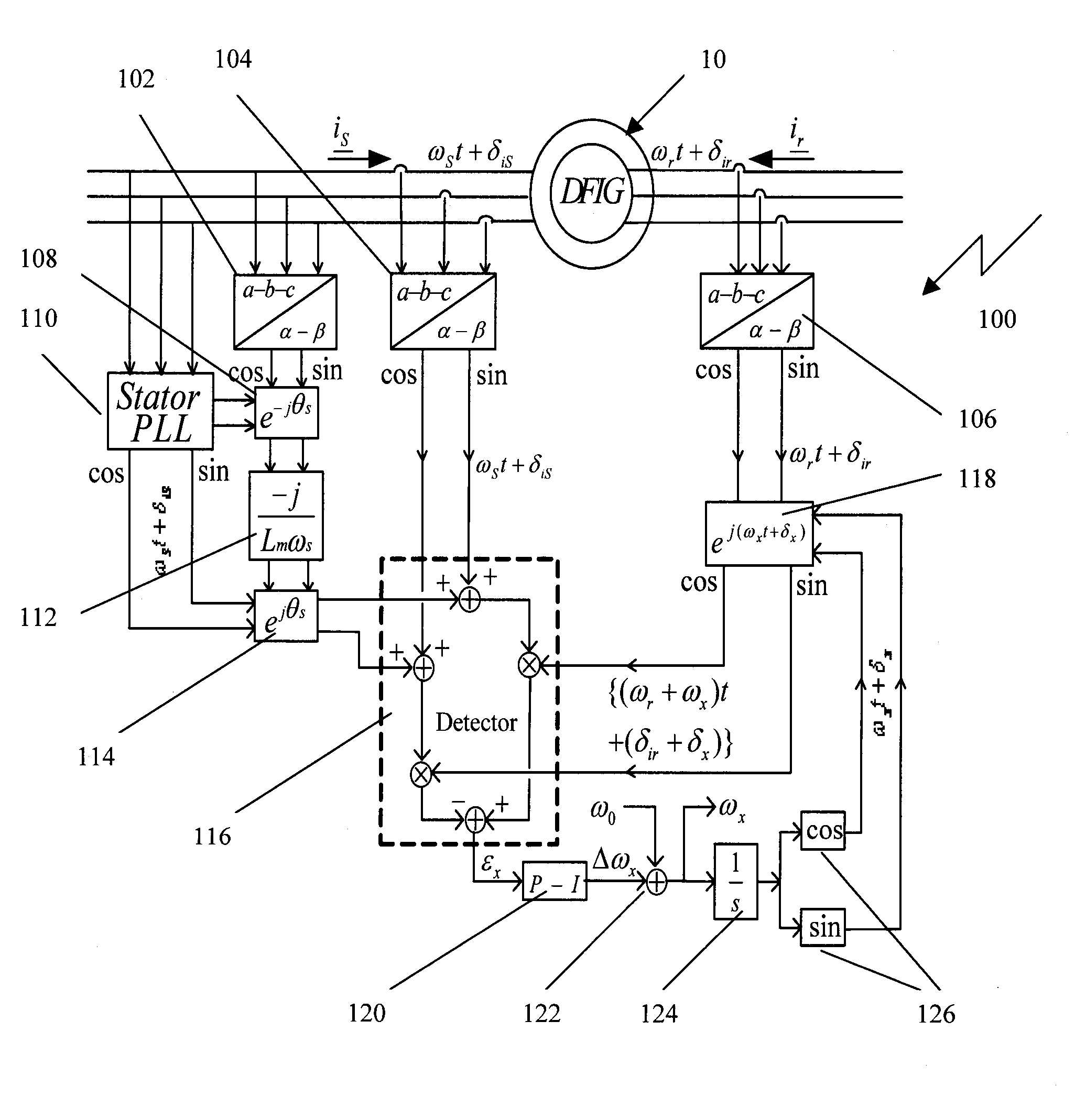
[0082]Referring to FIG. 6, a simplified block diagram of a Rotor Position PLL system 100 according to embodiments of the invention is shown. The Rotor Position PLL system 100 receives from transducers signals indicative of the 3-phase stator currents, the 3-phase rotor currents, and the 3-phase stator voltages and from the Stator PLL a signal indicative of the phase angle. The output signal is indicative of a rotor angular frequency and position θm=ωmt+δm. The 3-phase a-b-c quantities are converted to 2-phase α-β quantities in coordinate frame transformation blocks 102, 104, and 106 for the stator voltages, the stator currents, and the rotor currents, respectively. FIG. 6 depicts 2-phase information channels with cos(..) and sin(..) symbols under the transformation blocks denoting the channels containing the cosine and the sine of arguments. The arguments are the angles θx=ωxt+δx, θS=ωSt+δS, and θr=ωrt+δr for the channels of blocks 126, 104, and 106, respectively.
[0083]The operation...
second embodiment
[0104]Referring to FIG. 11, a simplified block diagram of a Rotor Position PLL system 300 according to embodiments of the invention is shown. The Rotor Position PLL 300 is similar in structure and function to the Rotor Position PLL 100, but is of simpler design at the cost reduced accuracy. However, the accuracy of the Rotor Position PLL 300 is still sufficient for numerous applications. The Rotor Position PLL 300 provides tracking of the rotor position absent mechanical sensors and does not rely on a machine parameter. It is noted, that in the description of the Rotor Position PLL 300 hereinbelow same reference numerals are used for same components performing a same function as in the description of the Rotor Position PLL 100.
[0105]The Rotor Position PLL system 300 receives from transducers signals indicative of the 3-phase stator currents and the 3-phase rotor currents. Typically, the transducers are for converting the rotor currents into transducer signals. The 3-phase a-b-c quan...
third embodiment
[0112]Referring to FIG. 15, a simplified block diagram of a Rotor Position PLL system 500 according to embodiments of the invention is shown. Noise in the position estimate δ is reduced first by the P-I block after εx—the output of the detector—and then by the [1 / jω] integrator block 124, which converts frequency ωx to angle δx. Reduction of noise requires a small proportional gain Kp. However, it is not possible to reduce Kp beyond a certain value without instability because of the large frequency range—−0.3ω0X0—within in which ΔωX varies. This range is due to the operation of the DFIG within ±0.3 slip. In order to reduce the range of frequency tracking, a double PLL design is used. The Rotor Position PLL system 500 comprises the same components as the Rotor Position PLL 100 but additionally a second PLL—detector 516. The upper PLL—detector 116 has a fixed center frequency at 60 Hz, i.e. ω01=120π. This PLL serves to track the wide range of operating frequency (1−0.3)×120πX1p1 and t...
PUM
 Abstract
Description
Claims
Application Information
 - R&D
- Intellectual Property
- Life Sciences
- Materials
- Tech Scout
- Unparalleled Data Quality
- Higher Quality Content
- 60% Fewer Hallucinations
Browse by: Latest US Patents, China's latest patents, Technical Efficacy Thesaurus, Application Domain, Technology Topic, Popular Technical Reports.
© 2025 PatSnap. All rights reserved.Legal|Privacy policy|Modern Slavery Act Transparency Statement|Sitemap|About US| Contact US: help@patsnap.com


