
Amplifier device and predistortion control method

a power amplifier and predistortion control technology, applied in the field of digital predistortion linearization of nonlinear devices, can solve the problems of inevitability of nonlinear distortion, low efficiency of vector methods, and distortion of output signals, so as to accelerate algorithm convergence, enhance performance, and effectively remove the effect of nonlinearity and memory effect of pa

Inactive Publication Date: 2013-06-25
FUJITSU LTD
View PDF8 Cites 4 Cited by
  • Summary
  • Abstract
  • Description
  • Claims
  • Application Information

AI Technical Summary

Benefits of technology

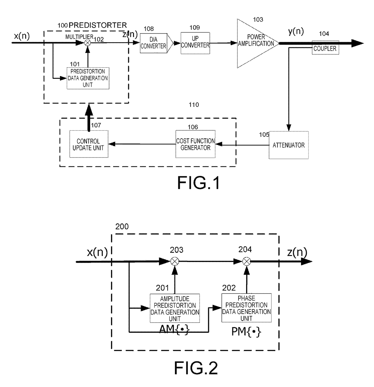
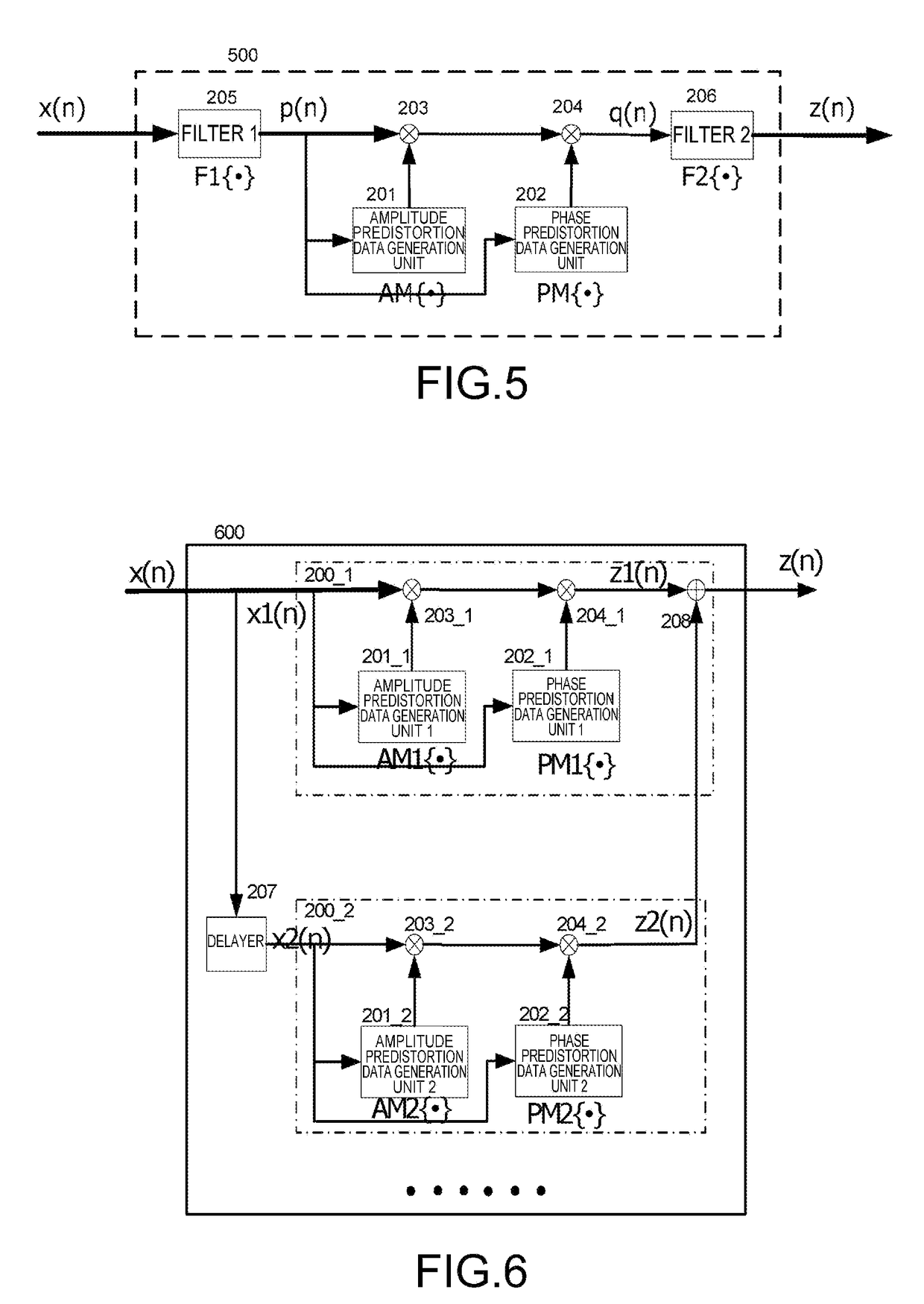
[0026]Embodiments of the present invention propose two scalar method based predistorter structures capable of counteracting memory effect, whereby nonlinearity and memory effect of the PA can be effectively removed.
[0027]Considering that the amplitude, phase and memory characteristics of the PA each has independent cost functions relevant thereto, embodiments of the present invention propose to generate a plurality of cost functions by processing digital domain feedback signals, and to optimize various sub-functional modules in the predistorter on a one-by-one basis, to thereby achieve the objective of accelerating algorithm convergence.
[0028]The amplifier device according to the embodiments of the present invention can be removed of memory effect to thereby enhance performance thereof under link structure of the scalar method.

Problems solved by technology

But when the envelope of the input signal fluctuates to the nonlinear region, the output signal will be distorted.
With the advent of new modulation schemes, dynamic range of the signal envelope becomes larger and larger, so that the occurrence of nonlinear distortion is inevitable.
The vector method is relatively high in cost because it demands precise feedback signal and demands precise synchronization of the input signal with the feedback signal.
However, the traditional scalar method does not take memory effect into consideration.
As a result, the performance of predistorter employing the conventional predistortion technique is far from being ideal.

Method used


Image

  • Amplifier device and predistortion control method
  • Amplifier device and predistortion control method
  • Amplifier device and predistortion control method

Examples


Embodiment Construction

[0045]Embodiments of the present invention are described in detailed below with reference to the drawings.

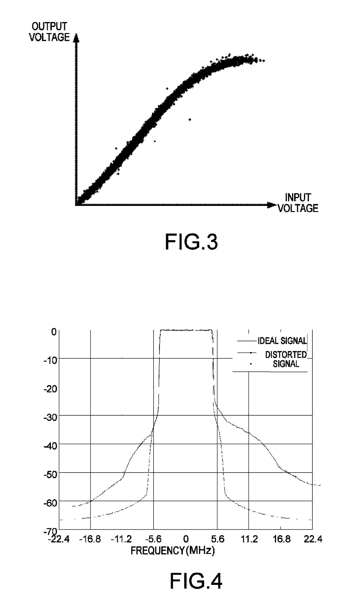
[0046]The inventors studied memory effect during the development of the present invention. FIG. 3 schematically illustrates manifestation of memory effect in the time domain in a power amplifier. In FIG. 3, the horizontal axis represents the voltage of the input signal into the PA, and the vertical axis represents the voltage of the output signal. As can be seen from FIG. 3, the curve is “very fat”, that is, a plurality of input signal amplitudes (voltage) correspond to one output signal amplitude (voltage). This is so because the current output value of PA is not only related to the current input value, but also related to previous input values.

[0047]FIG. 4 schematically illustrates manifestation of memory effect in the frequency domain in a power amplifier. In FIG. 4, the vertical axis represents normalized power spectrum density, and the horizontal axis represents frequency. ...


PUM


Abstract

This invention relates to an amplifier device and a predistortion control method. The amplifier device comprises a predistortion unit, a predistortion control unit, and an amplifier unit, of which the predistortion control unit controls the predistortion unit in accordance with a signal fed back from the amplifier unit. The predistortion control method comprises determining power of a left side lobe of two side lobes of a frequency spectrum of the signal fed back from the amplifier unit; determining power of a right side lobe of two side lobes of a frequency spectrum of the signal fed back from the amplifier unit; determining a cost function in accordance with the power of the first and right side lobes, and controlling the predistortion unit in accordance with the cost function.

Description

FIELD OF THE INVENTION[0001]The present invention relates to digital predistortion linearization of nonlinear devices, and more particularly to linearization of a power amplifier with memory effect.BACKGROUND OF THE INVENTION[0002]The power amplifier (PA) is an important component part in an electronic device, as it can amplify the power of a weak electric signal to satisfy the need of transmission and emission. The energy for amplification comes from a DC power source, i.e. the PA converts DC energy into an AC signal to enable the power intensity of the AC signal to satisfy the demand. The capacity for the PA to convert the DC energy into AC energy is referred to as efficiency of the PA. The input / output signal power relation of the PA can be divided into a linear region, a nonlinear region and a saturated region.[0003]When the envelope of an input signal fluctuates only in the linear region, the input signal is ideally amplified. But when the envelope of the input signal fluctuate...

Claims


Application Information

Patent Timeline
Patent Type & Authority Patents(United States)
IPC IPC(8): H04L25/03H04L25/49
CPCH03F1/3247H03F1/3282H03F3/24H03F3/189H03F2201/3233
Inventor SHI, ZHANLI, HUIZHOU, JIAN MINSUN, GANGWANG, ZHIQI
Owner FUJITSU LTD
Learn More