
Electric power steering apparatus

a technology of electric power steering and electric motor, which is applied in the direction of non-deflectable wheel steering, underwater vessels, special data processing applications, etc., can solve the problems of consuming more than necessary energy of auxiliary power supply, charging the power supply having a low amount of remaining electric energy, and charging control poses a substantial load on the control circuit of the electric power steering apparatus

Active Publication Date: 2013-06-18
JTEKT CORP
View PDF6 Cites 7 Cited by
  • Summary
  • Abstract
  • Description
  • Claims
  • Application Information

AI Technical Summary

Benefits of technology

The present invention is about an electric power steering system that can save energy by efficiently using its auxiliary power supply. This is achieved by controlling the amount of discharge from the auxiliary power supply according to the difference between the command value of the drive voltage and the previous value. By doing so, the system ensures an adequate voltage supply and prevents an excessive voltage supply. Additionally, the system performs accumulation operation to smooth the fluctuation of the drive voltage and avoids unnecessary charging of the auxiliary power supply. Overall, the system improves energy utilization and reduces energy waste.

Problems solved by technology

However, it takes some time to charge the power supply having a low amount of remaining electric energy.
Furthermore, charge control poses a substantial load on a control circuit for the electric power steering apparatus.
If the auxiliary power supply operates at full capacity even when the power shortage is moderate, the auxiliary power supply is activated excessively as a result, and the energy of the auxiliary power supply is consumed more than necessary.

Method used


Image

  • Electric power steering apparatus
  • Electric power steering apparatus
  • Electric power steering apparatus

Examples


Embodiment Construction

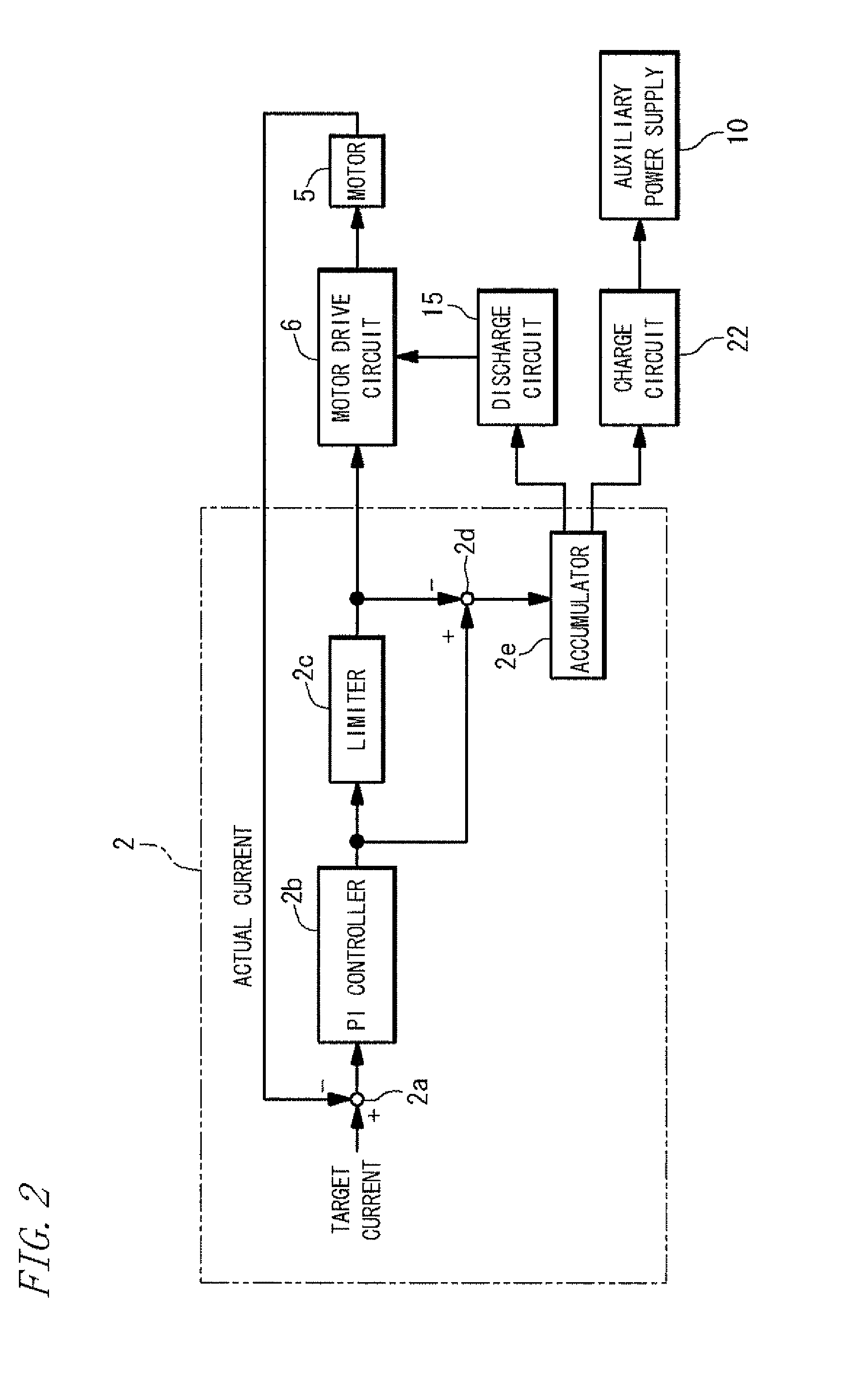
[0015]FIG. 1 is a circuit diagram principally showing an electric circuit of a general arrangement of an electric power steering apparatus 1 according to one embodiment of the present invention. Referring to the figure, a steering apparatus 3 is driven by a steering torque applied to a steering wheel 4 by a driver and a steering assist force generated by a motor 5. The motor 5 is a 3-phase brushless motor which is driven by a motor drive circuit (inverter) 6. The motor drive circuit 6, the internal configuration of which is not shown, includes six switching devices constituting a 3-phase bridge circuit, and a drive circuit for switching on and off these devices. This motor drive circuit 6 is controlled by a control circuit 2.

[0016]The motor drive circuit 6 is connected to a negative electrode of a battery 7 via a ground-side electrical conduction path LG. The battery 7 serves as a main power supply for supplying electric power to the motor drive circuit 6. The battery 7 is connected...


PUM


Abstract

In an electric power steering apparatus of the invention, a control circuit determines a command value of drive voltage supplied to a motor drive circuit based on an actual current through a motor and a target current. When the command value exceeds the previous value having a lower limit equivalent to a limit value representing the limit of the power supply from a battery, the control circuit controls the amount of discharge from the auxiliary power supply according to a difference between the command value and the previous value by increasing or decreasing a duty of switching devices. Thus, the power steering apparatus can save the energy of the auxiliary power supply for efficiently using the auxiliary power supply.

Description

TECHNICAL FIELD[0001]The present invention relates to an electric power steering apparatus that is mounted in a vehicle and generates a steering assist force by a motor.BACKGROUND ART[0002]Electric power steering apparatus is a machine which operates the motor for generating the steering assist force according to a steering torque applied by a driver. Recently, such an electric power steering apparatus has been faced with a demand for high power operation. To meet this demand, there has been proposed an electric power steering apparatus wherein an auxiliary power supply independent from a battery is connected in series to the battery as needed so as to supply high electric power at high voltage (see, for example, Patent Document 1).[0003]An electric double-layer capacitor, for example, may be used as the above auxiliary power supply. Such an auxiliary power supply must always be charged so as to be ready for use. However, it takes some time to charge the power supply having a low am...

Claims


Application Information

Patent Timeline
Patent Type & Authority Patents(United States)
IPC IPC(8): H02J7/00B62D6/00B62D5/04H02P5/00B62D119/00B62D127/00H02P6/06H02P6/08
CPCB62D5/0457B62D5/046B62D5/0475H02P6/085
Inventor OYA, TOSHIAKI
Owner JTEKT CORP
Learn More