
Stability indicator for a wireless repeater

a repeater and stability indicator technology, applied in the field of repeaters in wireless communication systems, can solve the problems of control metric indicating instability in the feedback loop of the repeater, and achieve the effect of improving repeater capability and monitoring feedback loop stability

Inactive Publication Date: 2013-06-11
QUALCOMM INC
View PDF51 Cites 0 Cited by
  • Summary
  • Abstract
  • Description
  • Claims
  • Application Information

AI Technical Summary

Benefits of technology

The patent describes a method for improving the stability of a wireless repeater by measuring the feedback loop between the transmitting and receiving antennas. By monitoring the size of the feedback control metric, the system can detect any instability in the repeater and take appropriate action to ensure a stable communication link. This results in better reliability and performance of the wireless network.

Problems solved by technology

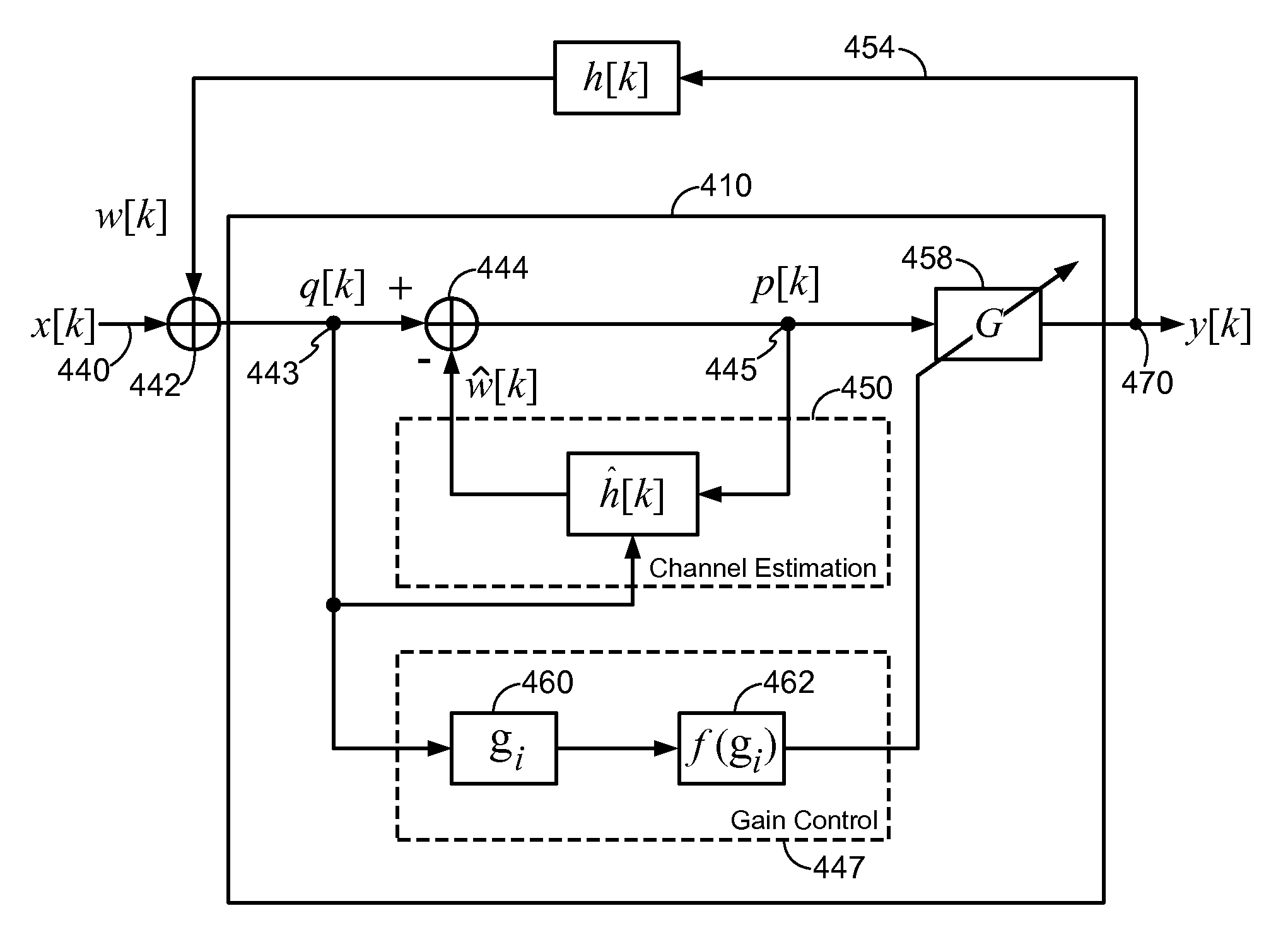
In operation, a large magnitude of the gain control metric indicates instability in the feedback loop of the repeater.

Method used


Image

  • Stability indicator for a wireless repeater
  • Stability indicator for a wireless repeater
  • Stability indicator for a wireless repeater

Examples


Embodiment Construction

[0037]The nature, objectives, and advantages of the disclosed method and apparatus will become more apparent to those skilled in the art after considering the following detailed description in connection with the accompanying drawings.

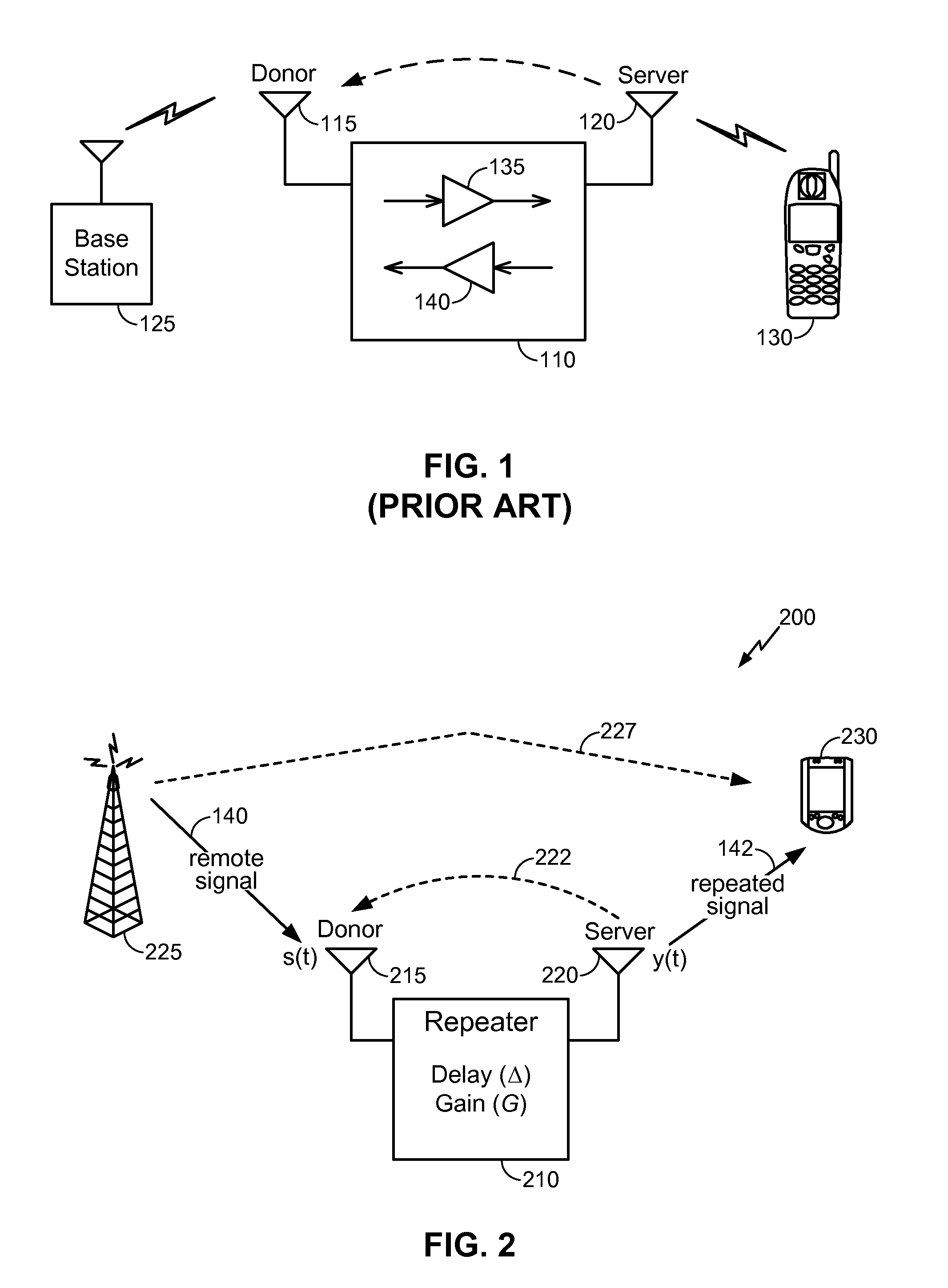
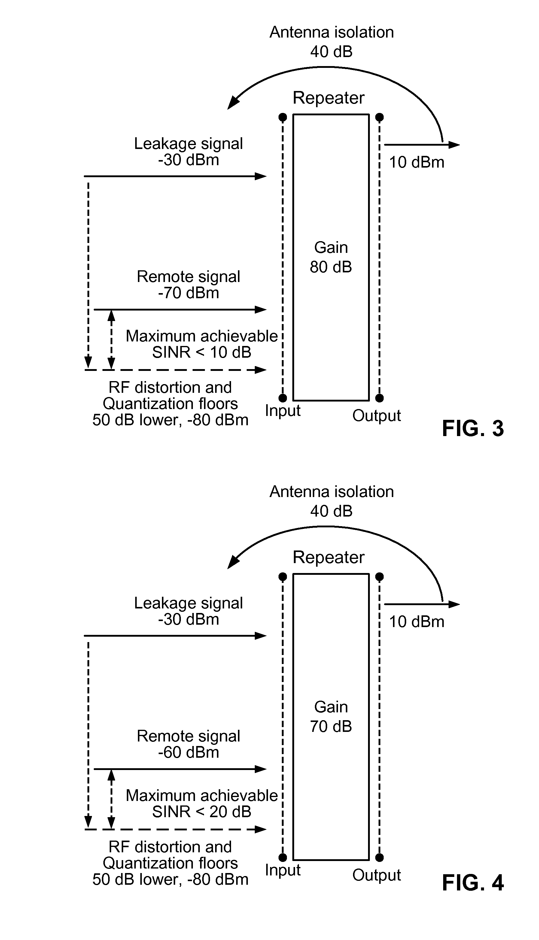
[0038]Prior art repeaters such as those described above may provide significant advantages for cellular telephone or similar networks. However, existing repeater configurations may not be suitable for some applications. For example, existing repeater configurations may not be suitable for indoor coverage applications (e.g., repeating signals for a residence or business environment) which may be more difficult to obtain the desired isolation between the repeater's antennas. Moreover, in some traditional repeater implementations, the target is to achieve as high a gain as reasonable while maintaining a stable feedback loop (loop gain less than unity). However, increasing the repeater gain renders isolation more difficult due to the increased signal leaki...


PUM


Abstract

A method for monitoring feedback loop stability in a wireless repeater includes measuring a gain control metric in the feedback loop of the repeater periodically for a given time period where the gain control metric is indicative of a loop gain of the feedback loop of the repeater; and monitoring the magnitude of the gain control metric to determine the stability of the feedback loop of the repeater. In operation, a large magnitude of the gain control metric indicates instability in the feedback loop of the repeater.

Description

CROSS-REFERENCE TO RELATED APPLICATIONS[0001]This application claims the benefit of U.S. Provisional Patent Application Ser. No. 61 / 177,209, filed on May 11, 2009, which application is incorporated herein by reference in its entirety.[0002]This application is related to the following concurrently filed and commonly assigned U.S. patent applications: application Ser. No. 12 / 722,714, entitled “Gain Control Optimizing SINR and Data Rate For Wireless Repeater”; application Ser. No. 12 / 722,722, entitled “Multi-Metric Gain Control For Wireless Repeater”; application Ser. No. 12 / 722,733, entitled “Gain Control Metric Computation In A Wireless Repeater”; application Ser. No. 12 / 722,749, entitled “Gain Adjustment Stepping Control In A Wireless Repeater”; and application Ser. No. 12 / 722,760, entitled “Gain Control Metric Pruning In A Wireless Repeater”. The applications are incorporated herein by reference in their entireties.BACKGROUND[0003]1. Field[0004]This disclosure generally relates to ...

Claims


Application Information

Patent Timeline
Patent Type & Authority Patents(United States)
IPC IPC(8): H04B17/02H04B17/40
CPCH04B7/15578H04B7/14H04B17/40
Inventor WANG, MICHAEL MAOGORE, DHANANJAY ASHOKBARRIAC, GWENDOLYN DENISE
Owner QUALCOMM INC
Learn More