Device for converting mechanical impact energy into electrical energy with optimised efficiency
a technology of electrical energy and mechanical energy, applied in piezoelectric/electrostrictive transducers, thermal-pv hybrid energy generation, generators/motors, etc., can solve the problems of device not affording optimal recovery of energy and device not being adapted to be deformed optimally for impacts
- Summary
- Abstract
- Description
- Claims
- Application Information
AI Technical Summary
Benefits of technology
Problems solved by technology
Method used
Image
Examples
second embodiment
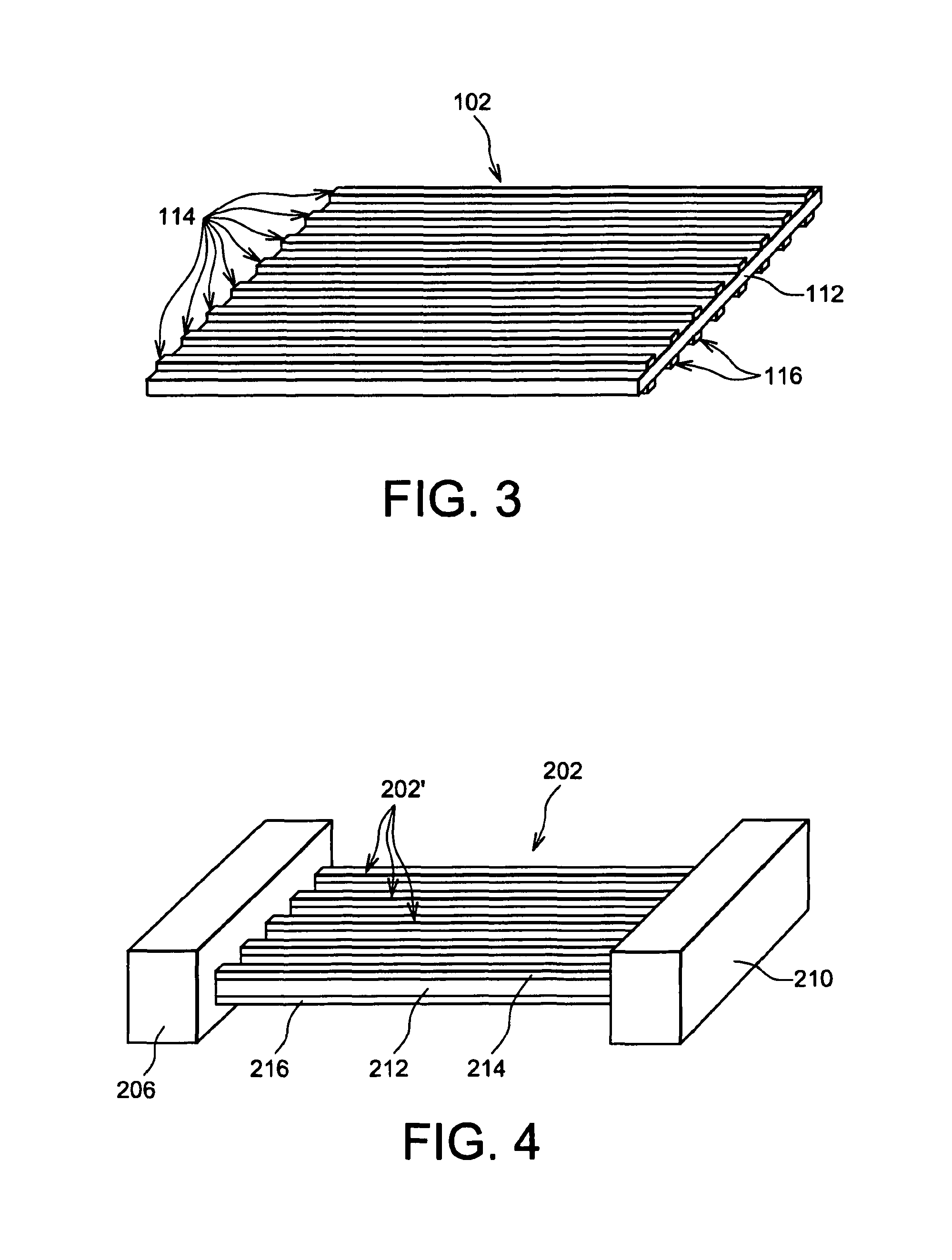
[0069]In FIG. 3, a membrane for an impact energy recovery device according to the present invention can be seen, and this embodiment is particularly advantageous since it optimises the quantity of energy recovered.
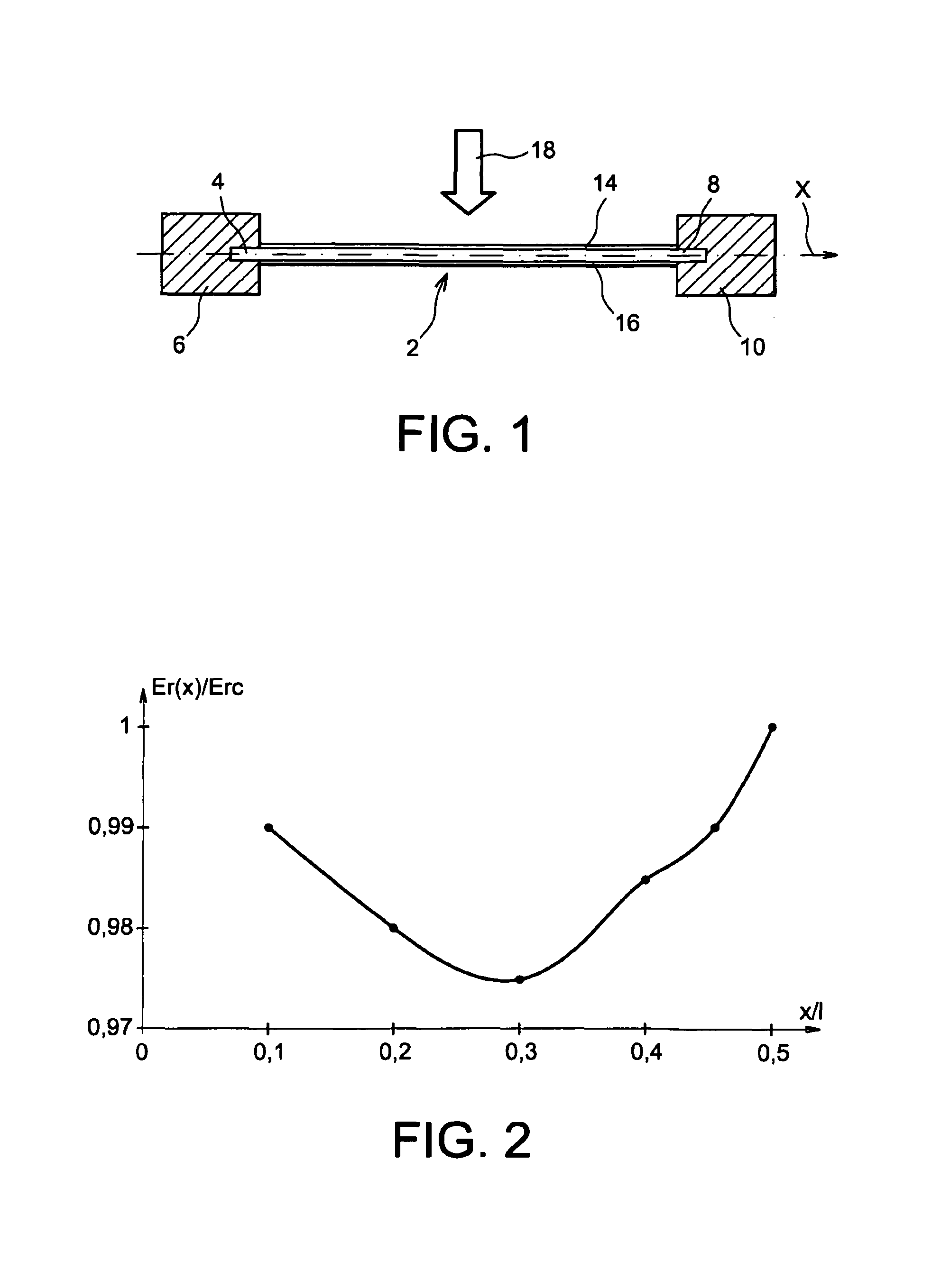
[0070]The membrane 102 shown in FIG. 3 comprises a core 112 made from material for transducing mechanical energy into electrical energy, on which there are disposed electrodes 114, 116 extending over the entire length of the top and bottom faces of the core 112 respectively.
[0071]According to this second embodiment, the membrane comprises several electrodes 114 disposed on the top surface of the core 112 and several electrodes 116 disposed on the bottom surface of the membrane 102.
[0072]Each electrode 114 is disposed at least partially vertically in line with an electrode 116.
first embodiment
[0073]These electrodes 114, 116 form parallel strips distributed over the entire width of the core 112, the electrodes 116 being disposed vertically in line with the electrodes 114. In the first embodiment, the electrodes 14, 16 form a continuous layer over each of the faces of the core 12 respectively.
[0074]This discrete distribution of the electrodes 114, 116 optimises the recovery of energy over the entire surface of the membrane 102, by limiting the movement of the charges and their symmetrical distribution.
[0075]This is because, when an object impacts the top surface of the membrane 2, the core 12 is deformed, giving rise to the generation of a voltage in the transducing material because of the asymmetry of the distribution of the charges.
[0076]The energy generated is then stored in electrical storage means, of the battery type.
[0077]In the case of the electrodes 14, 16 shown in FIG. 1 continuously covering the entire top surface and the entire bottom surface of the core 12, th...
third embodiment
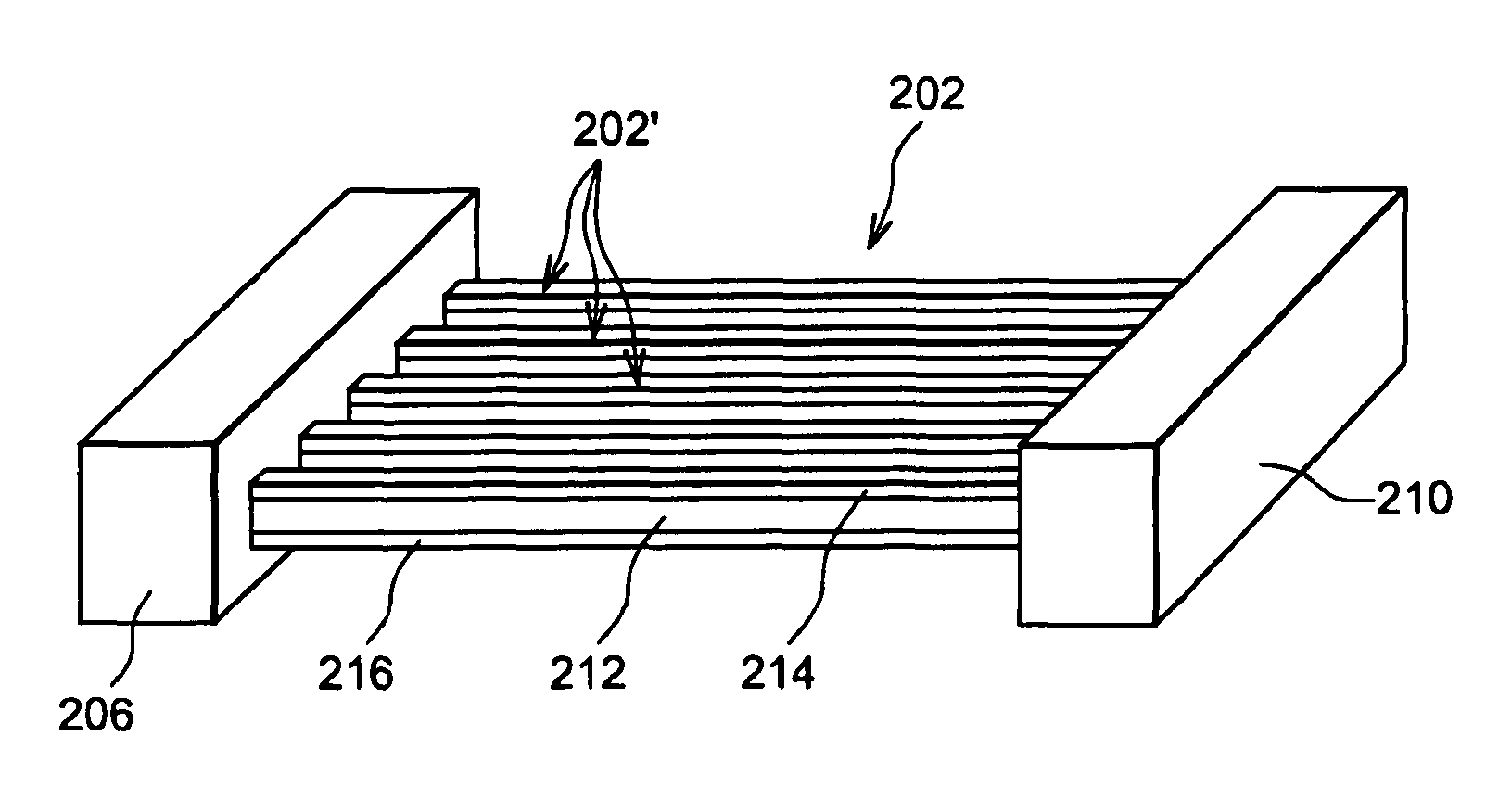
[0084]In FIG. 4, an impact energy recovery membrane can be seen.
[0085]The membrane 202 is, in this embodiment, formed by a plurality of discrete elements 202′ disposed parallel to one another and fixed at each of their longitudinal ends to supports 206, 208.
[0086]Each discrete element 202′ comprises a core 212 made from transducing material covered on each side by electrodes 214, 216 extending over the entire length of the core 212.
[0087]The widths of these elements 202′ forming strips or blades is substantially of the same order of magnitude as the diameter of the object the impact energy of which it is wished to recover.
[0088]According to this embodiment, each of the transducing elements is made mechanically independent. The deformation of each of the elements is increased with respect to the embodiments shown in FIGS. 1 and 3 since the stress involved in the impact of the object on an element 202′ is not “dampened” by a mechanical connection with the other elements 202′.
[0089]In ...
PUM
 Abstract
Description
Claims
Application Information
 - R&D
- Intellectual Property
- Life Sciences
- Materials
- Tech Scout
- Unparalleled Data Quality
- Higher Quality Content
- 60% Fewer Hallucinations
Browse by: Latest US Patents, China's latest patents, Technical Efficacy Thesaurus, Application Domain, Technology Topic, Popular Technical Reports.
© 2025 PatSnap. All rights reserved.Legal|Privacy policy|Modern Slavery Act Transparency Statement|Sitemap|About US| Contact US: help@patsnap.com


