
Wheel suspension for motor vehicles

a technology for motor vehicles and suspensions, applied in the direction of shock absorbers, transportation items, loading/unloading vehicle arrangment, etc., can solve the problems of bellows substantially collapsed or even burst, springs that do not reach the service life, and filter clogging sooner or later, so as to prevent external influences and keep functional interruptions or corrosion damage

Inactive Publication Date: 2013-06-04
AUDI AG
View PDF29 Cites 10 Cited by
  • Summary
  • Abstract
  • Description
  • Claims
  • Application Information

AI Technical Summary

Benefits of technology

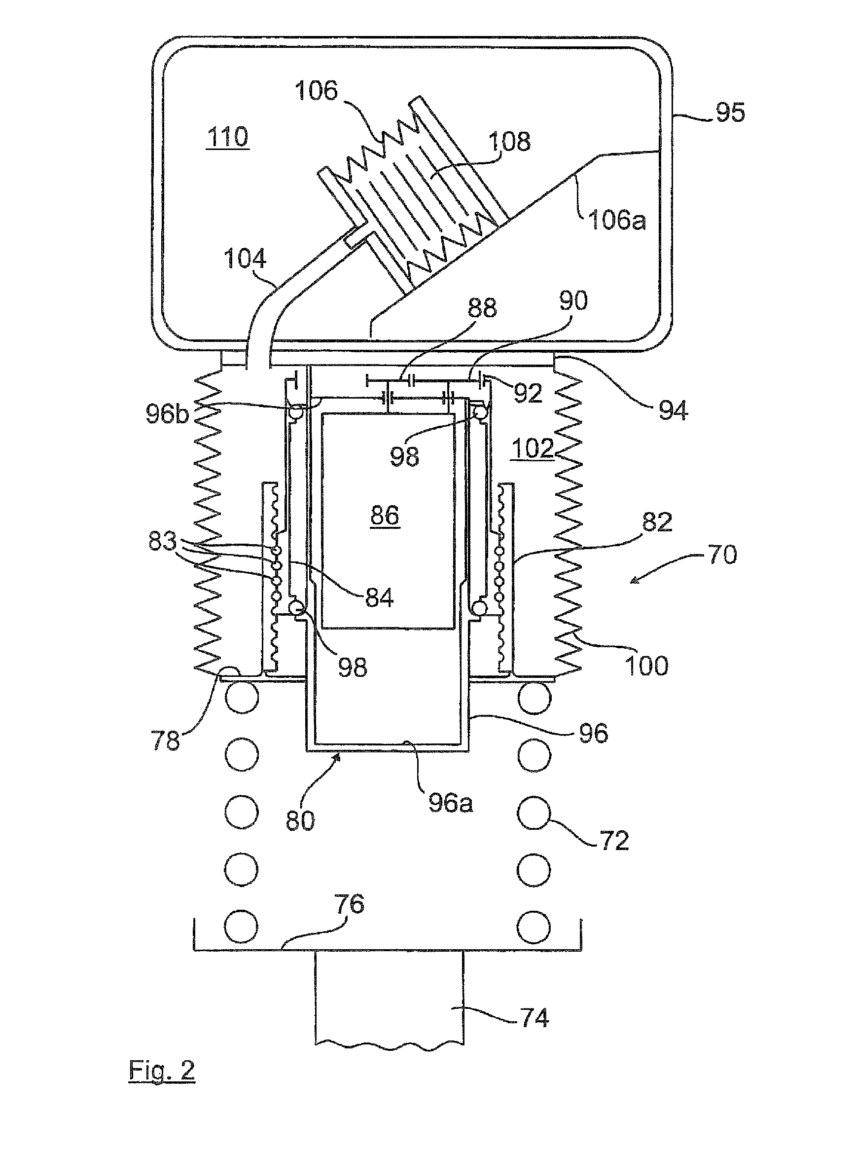
The invention proposes a solution for compensating for pressure fluctuations in a vertical adjusting device used in a wheel suspension system of a vehicle. The solution involves creating an auxiliary volume outside of the vertical adjusting device, which is connected to the interior space through a bellows. This auxiliary volume acts as a compensating chamber that prevents any structural restrictions and protects the vertical adjusting device from dirt and foreign particles. The air volume flowing around the vertical adjusting device is hermetically sealed to the outside, preventing air exchange and condensation water formation. The compensating bellows acts as a compensation element, even when there is a change in motor vehicle level or temperature. The invention presents a structurally advantageous solution for compensating for pressure fluctuations in a wheel suspension system.

Problems solved by technology

In that case, the spring would not reach its service life and would break prematurely.
A disadvantage is the fact that the filter clogs sooner or later depending on the type of application, i.e. in what environment the motor vehicle moves.
If there is no longer any free air passage, the bellows would substantially collapse or even burst.
However, the biggest disadvantage is that the filter can no longer filter finer particles (smaller than sand).
If this principle were to be used in a mechanical adjustment which, for example, includes a sensitive ball screw mechanism, this would not be sufficient.
Furthermore, the filter is not capable to keep away moisture, condensation water or splash water.
Moisture would cause corrosion at the roller bearings and at the spindle / nut unit and would also destroy the ball screw mechanism.

Method used


Image

  • Wheel suspension for motor vehicles
  • Wheel suspension for motor vehicles
  • Wheel suspension for motor vehicles

Examples


Embodiment Construction

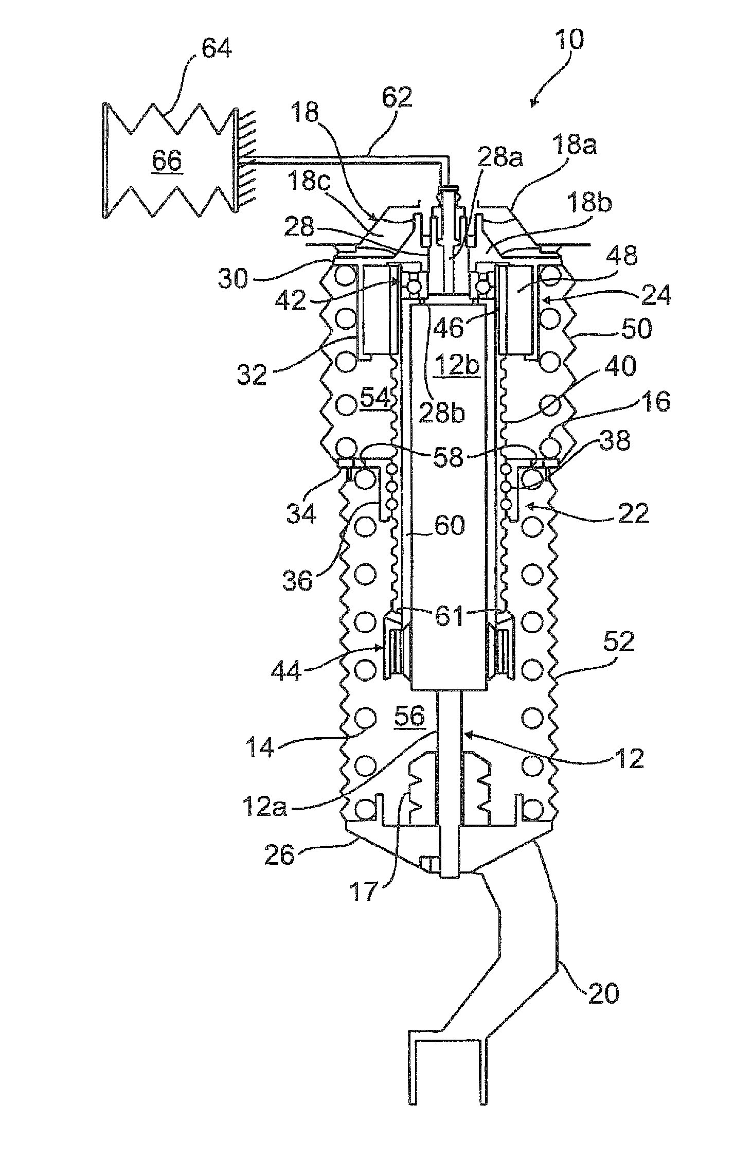
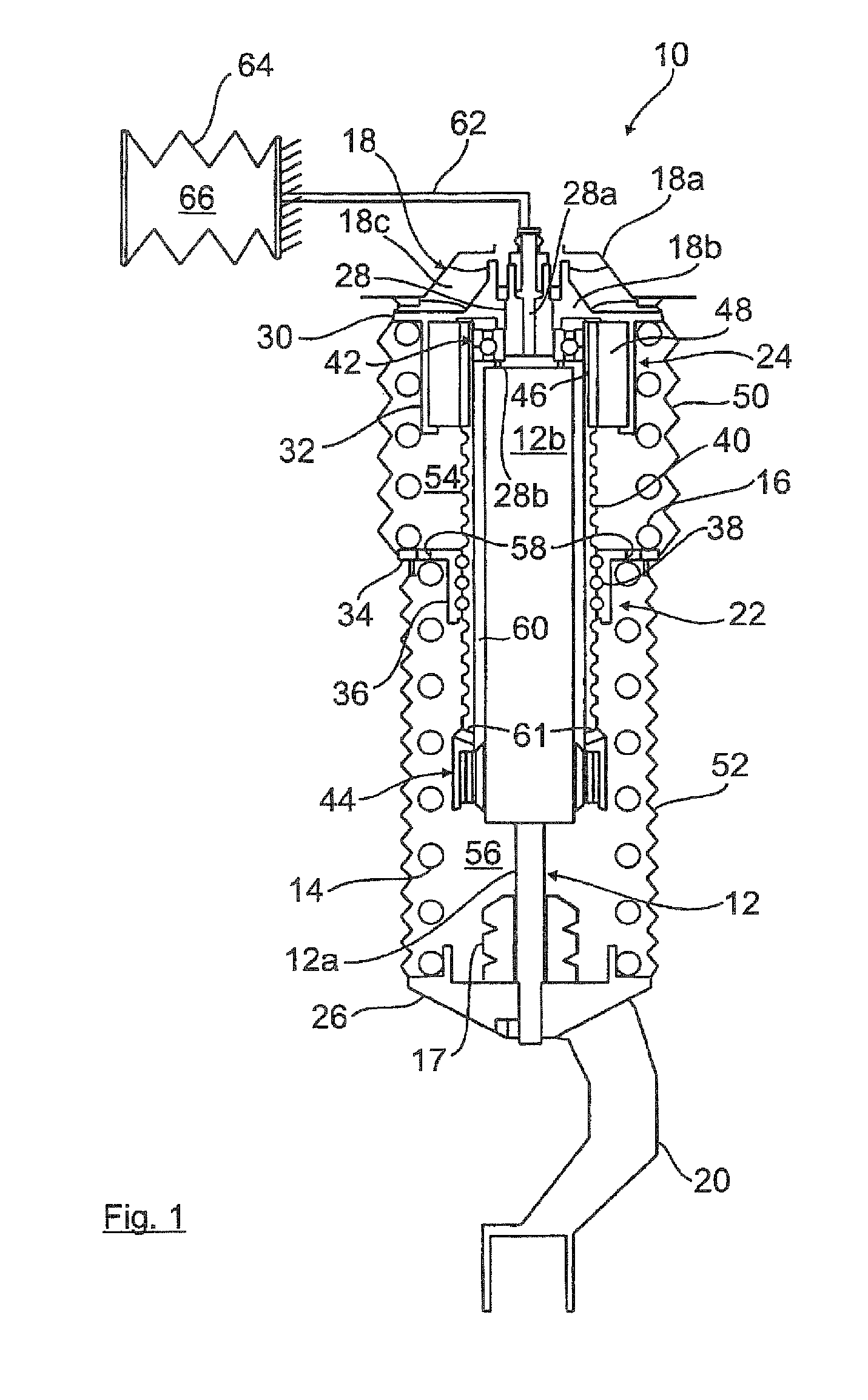
[0023]FIG. 1 schematically shows an active suspension strut 10 for a wheel suspension of motor vehicles which is essentially comprised of a telescopic shock absorber 12, a support spring 14, a storage spring 16, an upper shock-absorber bearing 18, and a lower shock-absorber support 20.

[0024]A level adjustment of the body of the motor vehicle and / or a roll and pitching stabilization are controlled by a vertical adjusting device 22 which is driven by an electric motor 24.

[0025]The shock absorber 12 is fastened with its downwardly protruding piston rod 12a to a lower plate spring 26. The plate spring 26 forms a structural unit with the shock-absorber support 20 which, in a known manner, is articulated or fastened to a wheel guide element of the wheel suspension of the motor vehicle, e.g. a suspension arm or a wheel carrier. In addition, a rubber-elastic contact buffer 17 is provided as additional spring at the plate spring 26.

[0026]The shock-absorber tube 12b of the shock absorber 12 i...


PUM


Abstract

The invention relates to a wheel suspension for motor vehicles with level adjustment of the body, having a vertical adjusting device (22; 80) which is disposed between a wheel guide element and the superstructure of the motor vehicle and which is particularly designed as a ball screw mechanism driven by an electric motor and acts on an adjusting plate spring (34) of at least one support spring (14), wherein the vertical adjusting device (22; 80) is outwardly sealed by at least one enclosing rubber-elastic bellows (50, 52; 100). In order to prevent deformation of the at least one bellows and ingress of dirt or moisture into the vertical adjusting device, the invention proposes that the interior space (54, 56; 102) enclosed by the bellows (50, 52; 100) is connected directly or indirectly to an auxiliary volume (66; 108) positioned outside of the bellows (50, 52; 100).

Description

CROSS-REFERENCES TO RELATED APPLICATIONS[0001]This application is the U.S. National Stage of International Application No. PCT / EP2009 / 006063, filed Aug. 21, 2009, which designated the United States and has been published as International Publication No. WO 2010 / 049026 A1 and which claims the priority of German Patent Application, Serial No. 10 2008 053 617.2, filed Oct. 29, 2008, pursuant to 35 U.S.C. 119(a)-(d).BACKGROUND OF THE INVENTION[0002]The invention relates to a wheel suspension for motor vehicles with level adjustment of the body.[0003]From DE 30 37 179, it is known to protect the piston rod in a telescopic shock absorber arrangement for wheel suspensions of motor vehicles by means of an outwardly sealed, rubber-elastic bellows against dirt and moisture, wherein the interior space of the bellows is connected to an auxiliary volume. The auxiliary volume is formed by a cylindrical tube which is arranged around the shock-absorber tube of the shock absorber, or possibly direct...

Claims


Application Information

Patent Timeline
IPC IPC(8): B60G17/04
CPCB60G15/065B60G17/021F16F9/049B60G2202/312B60G2202/32B60G2202/42B60G2204/40B60G2500/30
Inventor MICHEL, WILFRIED
Owner AUDI AG
Learn More