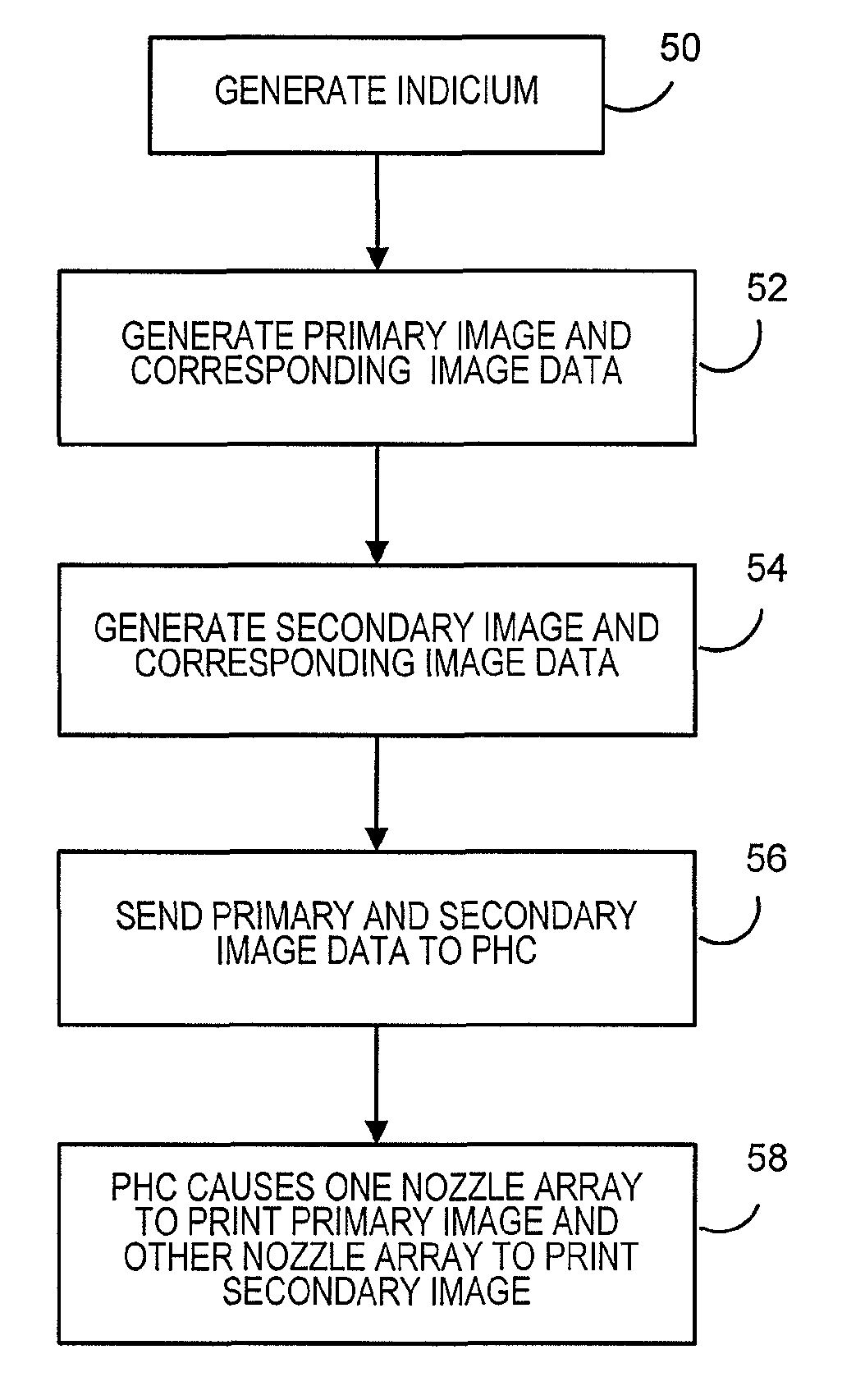
Method and system for providing evidence of printing in event of print head failure
a technology of print head and evidence, applied in the field of printing system, can solve the problem of not being able to detect secondary images, and achieve the effect of minimal likelihood of them being used
- Summary
- Abstract
- Description
- Claims
- Application Information
AI Technical Summary
Benefits of technology
Problems solved by technology
Method used
Image

Examples
Embodiment Construction
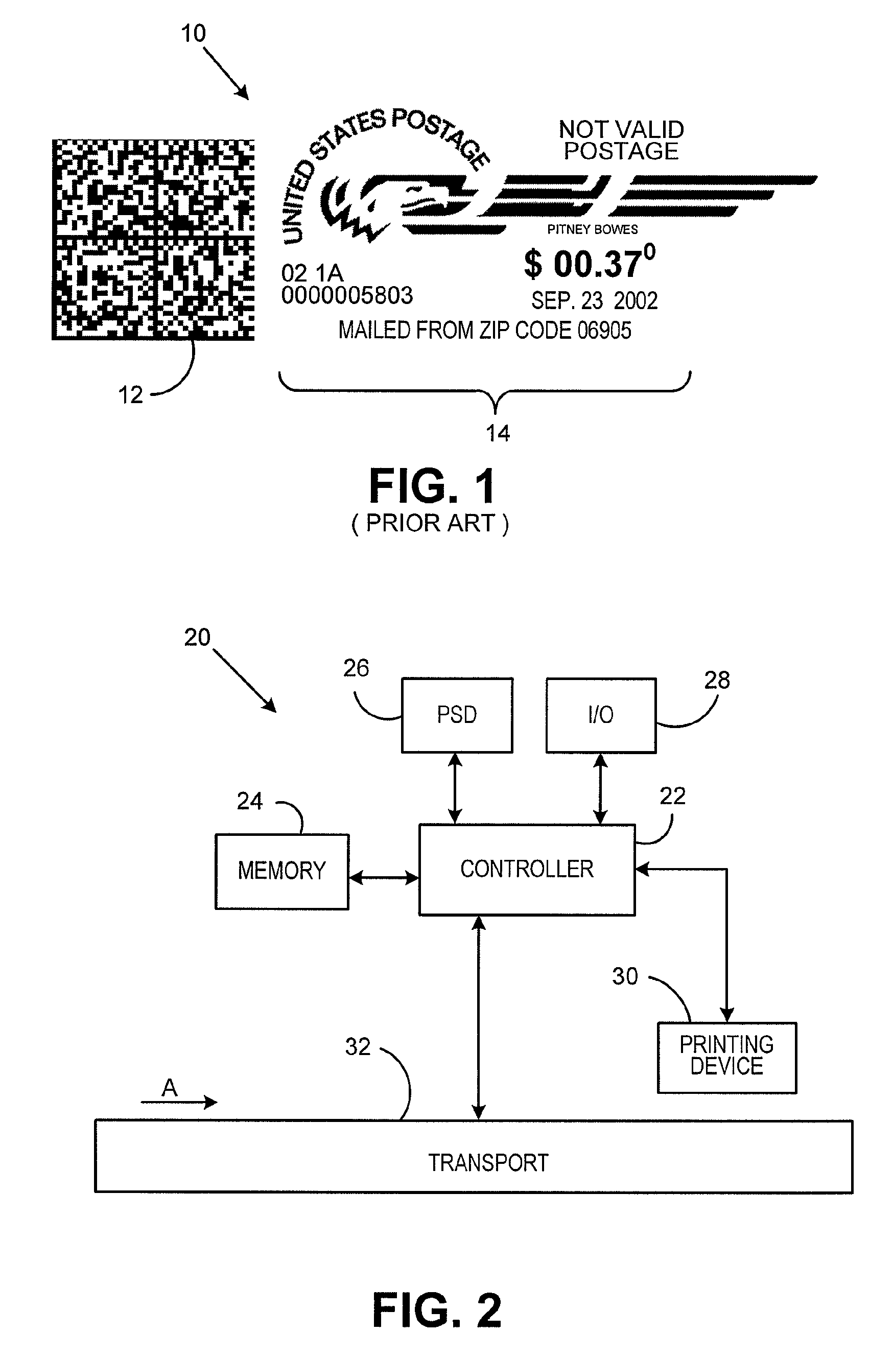
[0017]In describing the present invention, reference is made to the drawings, wherein there is seen in FIG. 2 a portion of a mail processing system 20 according to an embodiment of the present invention. It should be noted that while the following description is being made with respect to a mail processing system, the present invention is not so limited and can be utilized in any type of metering system that prints indicia that evidences payment. Mail processing system 20 includes a controller 22, that preferably includes one or more controller units, such as, for example, a microprocessor, general or special purpose processor or the like, to control operation of the mail processing system 20. A memory 24 is coupled to the controller 22 for storage of data and executable software programs accessed by the controller 22. A postal security device (PSD) 26 is coupled to the controller. The PSD 26 contains one or more registers that store the accounting information concerning usage, such...
PUM
 Abstract
Description
Claims
Application Information
 - R&D
- Intellectual Property
- Life Sciences
- Materials
- Tech Scout
- Unparalleled Data Quality
- Higher Quality Content
- 60% Fewer Hallucinations
Browse by: Latest US Patents, China's latest patents, Technical Efficacy Thesaurus, Application Domain, Technology Topic, Popular Technical Reports.
© 2025 PatSnap. All rights reserved.Legal|Privacy policy|Modern Slavery Act Transparency Statement|Sitemap|About US| Contact US: help@patsnap.com