Methods for reducing the width of the unbonded region in SOI structures
a technology of unbonded region and soi, which is applied in the direction of semiconductor/solid-state device testing/measurement, measurement devices, instruments, etc., can solve the problems of particle contamination potential source, and achieve the effects of reducing the roll-off amount (“roa”), more bonding, and strong bonding
- Summary
- Abstract
- Description
- Claims
- Application Information
AI Technical Summary
Benefits of technology
Problems solved by technology
Method used
Image


Examples
example 1
Unbonded Width of SOI Structures with Variable ROA
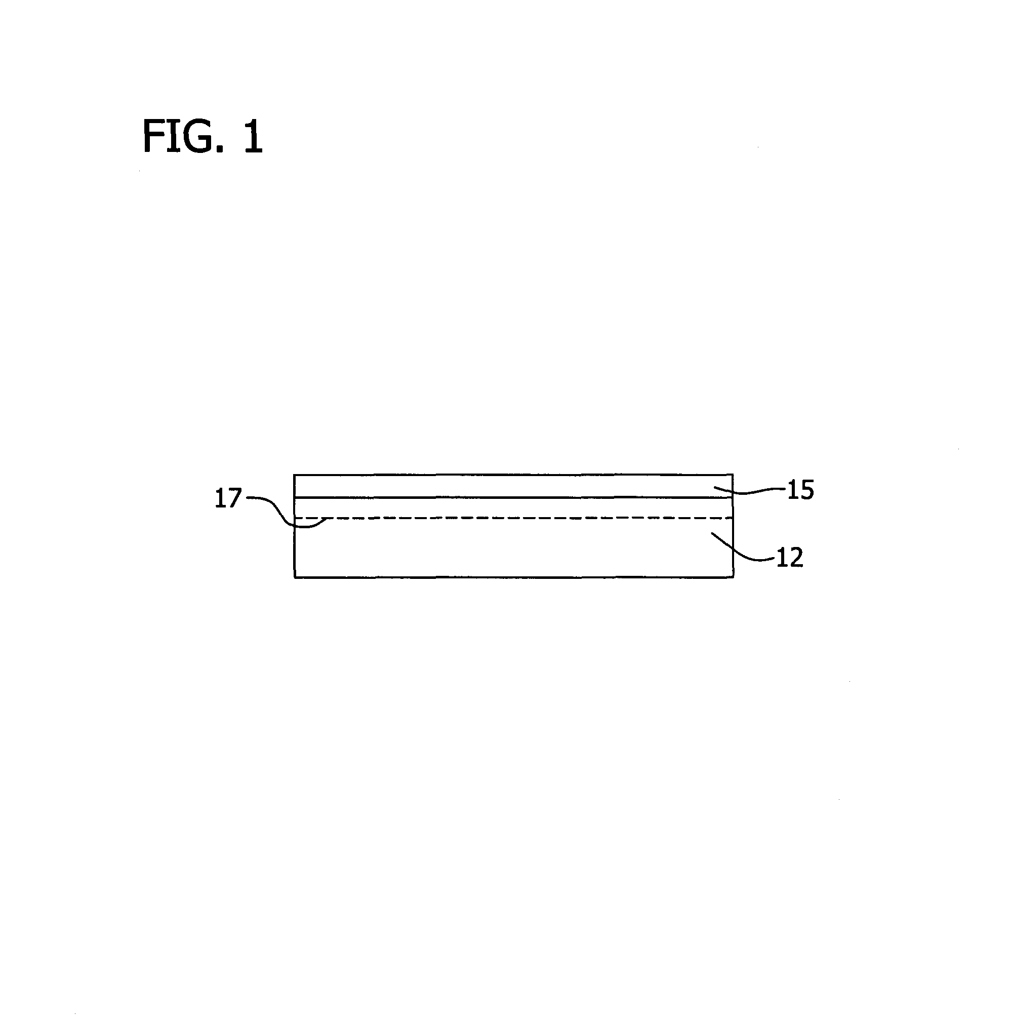
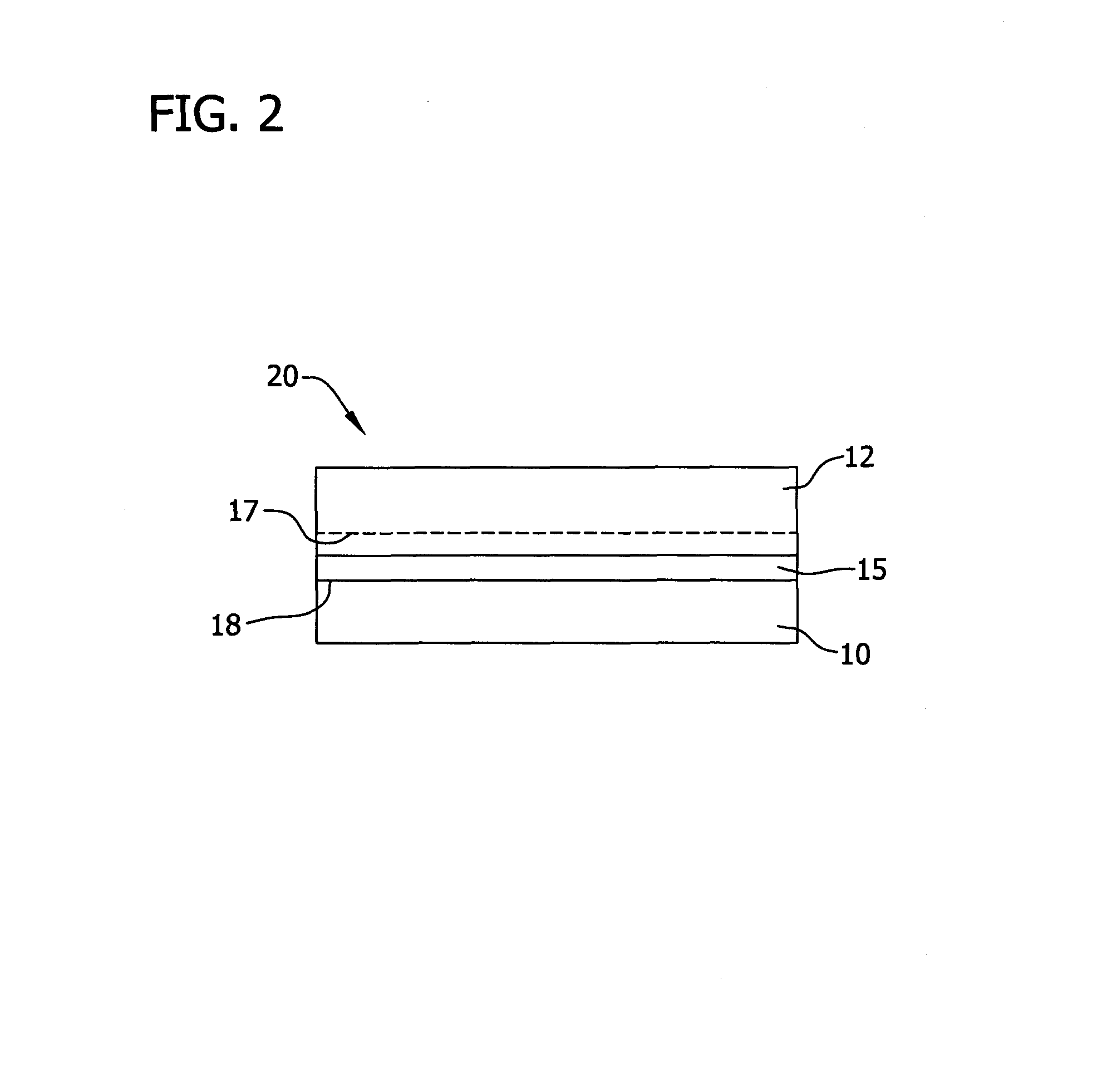
[0070]Six 300 mm SOI structures were prepared by bonding a handle wafer to a donor wafer with a dielectric layer (145 nm thick) on the surface of the donor wafer followed by cleaving along a cleave plane formed within the donor wafer. The cleave plane was formed in the donor wafer by implanting He+ ions at an energy of 36 keV and a dose of 1×10¹⁶ ions / cm2 followed by implanting H2+ ions at an energy of 48 keV and a dose of 5×10¹⁵ ions / cm2 (Quantum H Implanter (model Q843), Applied Materials (Santa Clara, Calif.)). Cleaving was performed by heating to 350° C. (A412 Furnace, ASM (Almere, The Netherlands)).
[0071]One pair of SOI structures was prepared from donor and handle wafers each having a thickness ROA of about −800 nm. Another pair was made from handle wafers with a thickness ROA of about −800 nm and donor wafers of about −200 nm. Another pair was made from handle and donor wafers each having a thickness ROA of about −200 nm. All ...
example 2
Comparison of Unbonded Width in SOI Structures Prepared from New and Conventional Donor Wafers and / or Handle Wafers
[0074]Four sets of 300 mm SOI structures were prepared from the various combinations of donor and handle wafers shown below:
[0075](a) conventional donor and conventional handle wafer (i.e., no cleaning step between rough polish and finish polish for donor or handle wafer);
[0076](b) new donor wafer (rough polish with a polyurethane foam pad followed by a cleaning step followed by finish polish with a polyurethane foam pad) and conventional handle wafer;
[0077](c) new donor wafer and handle wafer made by unknown process; and
[0078](d) new donor wafer and new handle wafer.
[0079]Two wafers from each group (a)-(d) were analyzed to determine the thickness ROA, front surface ROA and second derivative of the front surface shape (zdd). The thickness ROA of wafer groups (a)-(d) are graphically illustrated in FIG. 10. The front surface ROA of wafer groups (a)-(d) are graphically sho...
PUM
| Property | Measurement | Unit |
|---|---|---|
| size | aaaaa | aaaaa |
| size | aaaaa | aaaaa |
| surface roughness | aaaaa | aaaaa |
Abstract
Description
Claims
Application Information
 - R&D
- Intellectual Property
- Life Sciences
- Materials
- Tech Scout
- Unparalleled Data Quality
- Higher Quality Content
- 60% Fewer Hallucinations
Browse by: Latest US Patents, China's latest patents, Technical Efficacy Thesaurus, Application Domain, Technology Topic, Popular Technical Reports.
© 2025 PatSnap. All rights reserved.Legal|Privacy policy|Modern Slavery Act Transparency Statement|Sitemap|About US| Contact US: help@patsnap.com