Integrated sulfur recovery methods in power plants and low BTU gas fields

a technology of integrated sulfur recovery and gas field, which is applied in the direction of sulfur compounds, sulfur preparation/purification, machines/engines, etc., can solve the problems of high overall energy consumption, inconvenient gas processing, and inability to meet environmental regulations. achieve reasonable operating and capital costs, and reduce energy significantly

Active Publication Date: 2013-05-14
RAMESHNI MAHIN +1
View PDF2 Cites 23 Cited by
  • Summary
  • Abstract
  • Description
  • Claims
  • Application Information

AI Technical Summary

Benefits of technology

The invention describes a process for efficiently removing sulfur dioxide (SO2) from the exhaust gas of power plants or low-BTU gas fields. This is accomplished by first removing acid gases from the exhaust gas and then using a Claus reactor to convert the sulfur dioxide to sulfur. The recovered sulfur dioxide can then be reused in the production of other products. The process eliminates the need for expensive and energy-consuming equipment, reducing costs and ensuring near-100% sulfur recovery.

Problems solved by technology

The overall energy consumption is high, and meeting environmental regulations are costly.
With further aspects of the present innovation, there are many gas fields around the world that holds the Low BTU Gas which contains a very large gas volume and it is not economical to process the gas by using conventional methods to meet the pipeline specifications.
The gas has to be transported to other locations or facilities to remove high H2S, high Nitrogen and high CO2 content but due to a large gas volumetric it is not practical nor economical.

Method used


Image

  • Integrated sulfur recovery methods in power plants and low BTU gas fields
  • Integrated sulfur recovery methods in power plants and low BTU gas fields
  • Integrated sulfur recovery methods in power plants and low BTU gas fields

Examples


Embodiment Construction

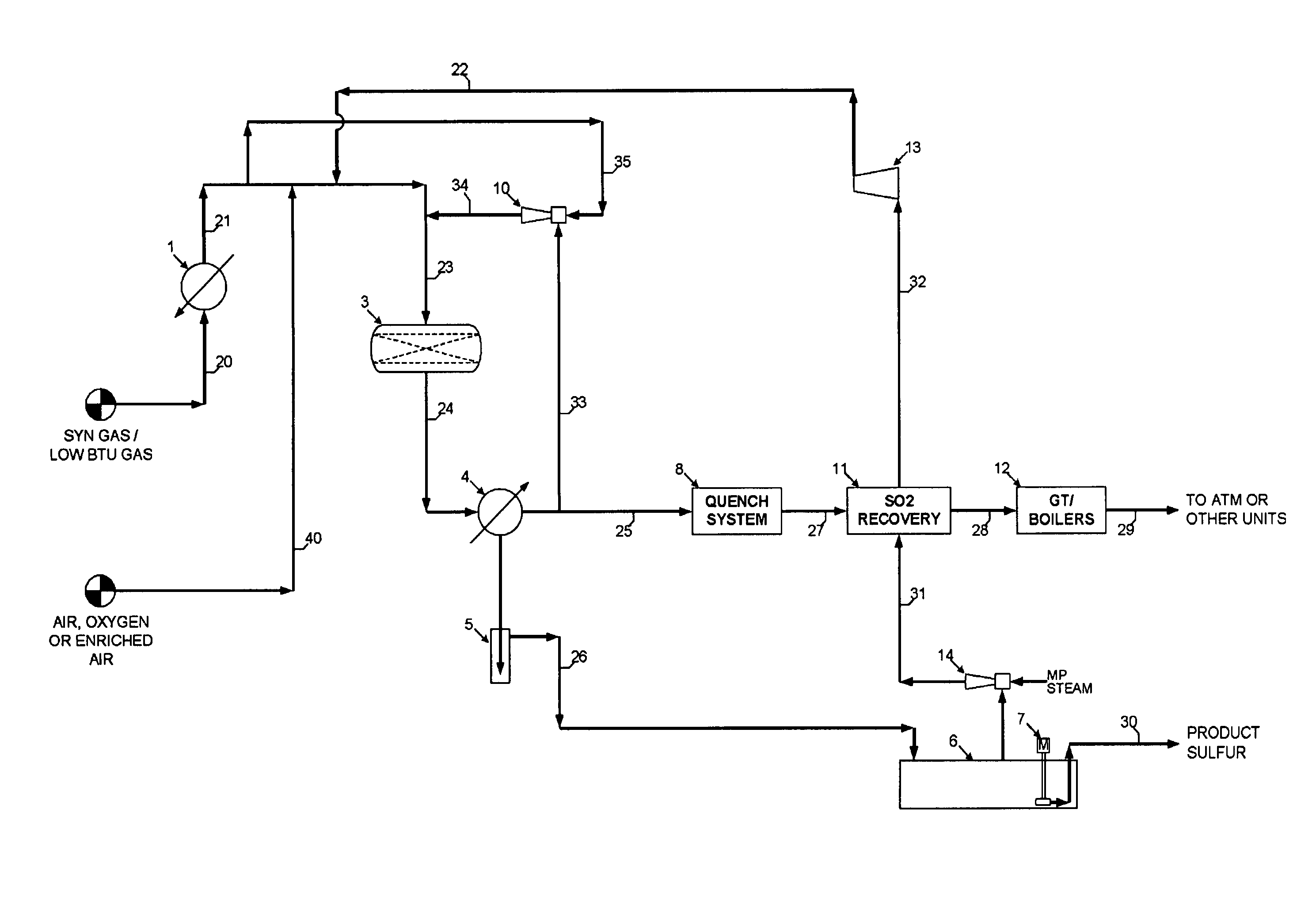
[0044]One or more illustrative embodiments incorporating the invention disclosed herein are presented below. Not all features of an actual implementation are described or shown in this application for the sake of clarity. It is understood that in the development of an actual embodiment incorporating the present invention, numerous implementation-specific decisions must be made to achieve the developer's goals, such as compliance with system-related, business-related, government related and other constraints, which vary by implementation and from time to time. While a developer's efforts might be complex and time-consuming, such efforts would be, nevertheless, a routine undertaking for those of ordinary skill the art having benefit of this disclosure.

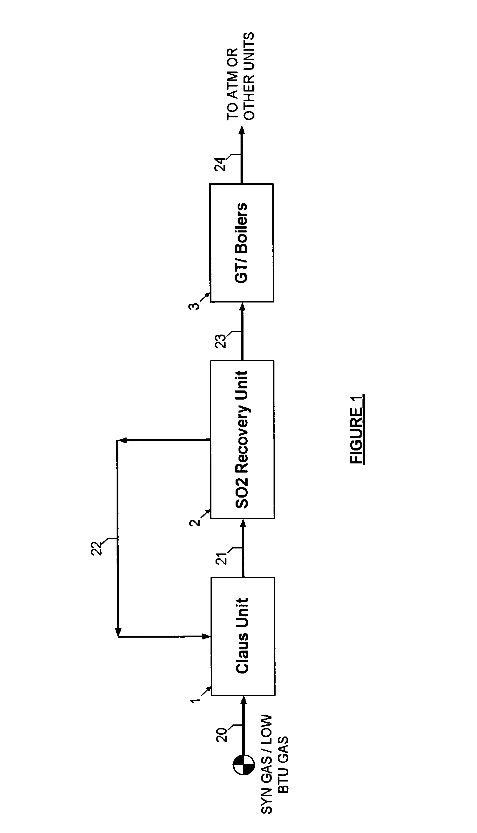
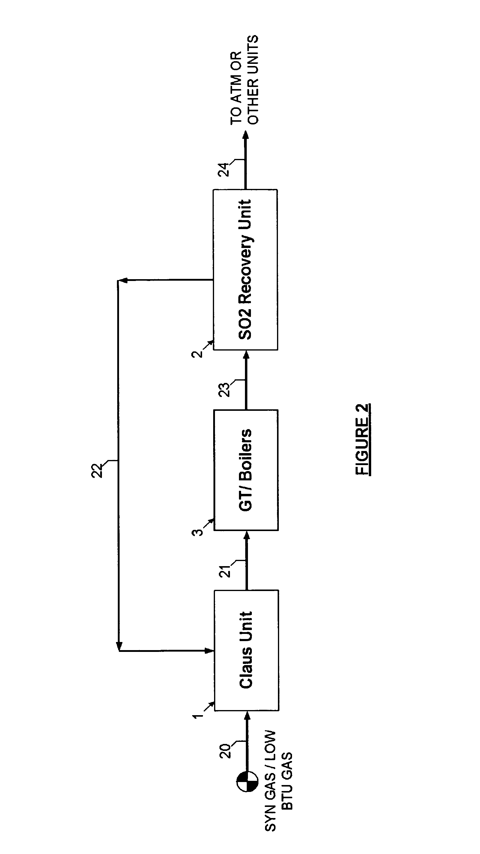
[0045]In general terms, Applicant has created new processes of sulfur recovery unit from the syngas in the power plants and from the Low BTU Gas fields by reducing some steps compare to the conventional gasification and Low BTU gas field...


PUM


Abstract

This disclosure relates generally to processes for the production of elemental sulfur from Syngas, in the power plant, or Low BTU Gas fields and more particularly to processes the mixture of the 100% syngas or low BTU stream with the 100% SO2 recycle gas; with an additional stream comprising oxygen such as air, oxygen-enriched air, or substantially pure oxygen is added to the SO2 recycle stream prior entering the Claus reactor for producing elemental sulfur. The combination of innovation schemes comprises the sulfur recovery unit, the SO2 recovery unit and the gas turbines or boilers to promote a cost effective options by reducing the number of steps in an efficient manner and to achieve near 100% sulfur recovery with significant cost and energy saving. The SO2 gas is recycled from the SO2 recovery unit to the sulfur recovery unit by using one of the regenerable solvent.

Description

CROSS REFERENCE TO RELATED APPLICATIONS[0001]Not ApplicableSTATEMENT REGARDING FEDERALLY SPONSORED RESEARCH OR DEVELOPMENT[0002]Not ApplicableREFERENCE TO SEQUENCE LISTING[0003]Not ApplicableREFERENCE TO A TABLE[0004]Not ApplicableREFERENCE TO A COMPUTER PROGRAM LISTING COMPACT DISK APPENDIX[0005]Not ApplicableBACKGROUND OF THE INVENTION[0006]This disclosure relates generally to processes for the production of elemental sulfur from Syngas, in the power plant, or Low BTU Gas fields and more particularly to processes the mixture of the 100% syngas stream with the 100% SO2 recycle gas; with an additional stream comprising oxygen such as air, oxygen-enriched air, or substantially pure oxygen is added to the SO2 recycle stream prior entering the Claus reactor for producing elemental sulfur. The combination of innovation schemes comprises the sulfur recovery unit, the SO2 recovery unit and the gas turbines or boilers to promote a cost effective options by reducing the number of steps in a...

Claims


Application Information

Patent Timeline
IPC IPC(8): C01B17/04
CPCC01B17/0404C01B17/0426F01K23/067C01B17/60Y02E20/18Y02E20/16Y02P20/10
Inventor RAMESHNI, MAHINSANTO, STEPHEN L.
Owner RAMESHNI MAHIN
Why Eureka
Try Eureka