
Shape-based object detection and localization system

Inactive Publication Date: 2013-05-07
HRL LAB
View PDF11 Cites 38 Cited by
  • Summary
  • Abstract
  • Description
  • Claims
  • Application Information

AI Technical Summary

Benefits of technology

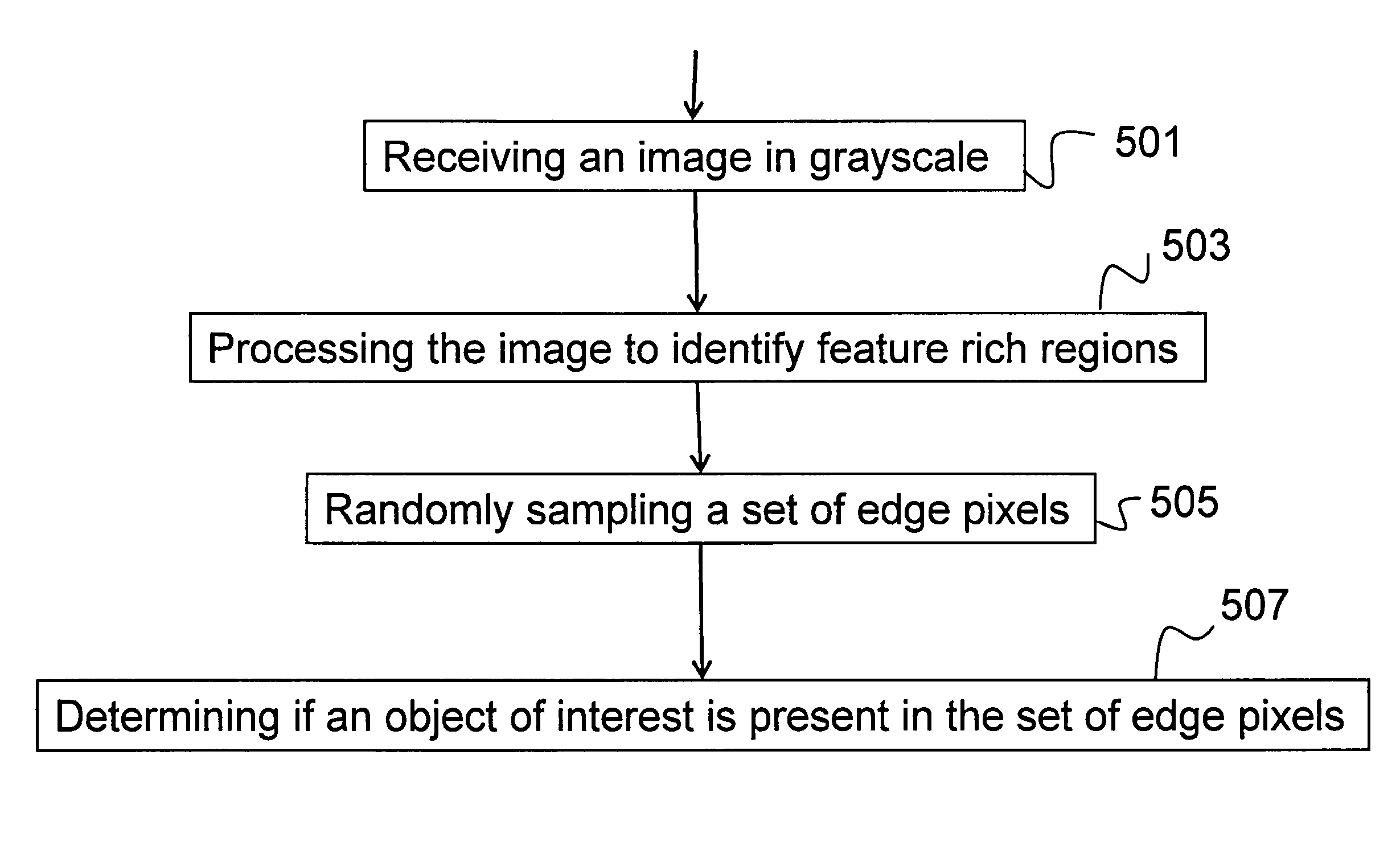
The present invention is a computer-implemented method for identifying a concealed object of interest. It involves processing an image to identify feature-rich regions which are processed to create a binary mask of the image. The binary mask is then used to determine if an object of interest is present in the image. The method includes steps to sample edges in the image, use an edge preserving non-linear diffusion to increase salinity of edges, form a background and foreground in the image, determine the distance between the background and an object of interest, and identify the object as an object of interest if the distance measurement is below a predetermined threshold. A computer program product and system for implementing this method are also provided.

Problems solved by technology

As such, these systems generate concerns in the public over privacy issues.
Although some attempts are being made at automating the process by device manufacturers such as Rapiscan Systems Inc. and Trex Enterprises Corporation, no fully automated system currently exists that can scan and reliably analyze two-dimensional (2D) image content for the presence of concealed objects.
The prior art is limited for these particular types of imagery.
The limitation is primarily due to availability and the need for use of such scanning modalities for security purposes in the public domain.
In the mmW and backscatter X-ray image analysis domain, device manufacturers have made attempts at bringing together a combination of off-the-shelf algorithms to analyze images for weapon detection, yet a reliable system does not currently exist that is able to detect weapons in such scans.
The existing methods are often not tailored to the specific nature of the data.
A literature and patent search on prior art has revealed related work, particularly in the area of medical imaging; however, as indicated herein, the methods used pose significant vulnerabilities to geometric deformations, image appearance variations and partial occlusions.

Method used


Image

  • Shape-based object detection and localization system
  • Shape-based object detection and localization system
  • Shape-based object detection and localization system

Examples


Embodiment Construction

[0027]The present invention relates to an object detection and localization system and, more particularly, to a system that localizes and detects an object based on the shape of the object. The following description is presented to enable one of ordinary skill in the art to make and use the invention and to incorporate it in the context of particular applications. Various modifications, as well as a variety of uses in different applications will be readily apparent to those skilled in the art, and the general principles defined herein may be applied to a wide range of embodiments. Thus, the present invention is not intended to be limited to the embodiments presented, but is to be accorded the widest scope consistent with the principles and novel features disclosed herein.

[0028]In the following detailed description, numerous specific details are set forth in order to provide a more thorough understanding of the present invention. However, it will be apparent to one skilled in the art...


PUM


Abstract

Described is a system for identifying a concealed object of interest. The system is initialized by receiving an image in grayscale. The image is processed image to identify feature rich regions, which are identified as a binary mask describing edge pixels and non-edge pixels. A set of edge pixels are then randomly sampled. An object detector function is then used on the set of edge pixels to determine if an object of interest is present in the set of edge pixels.

Description

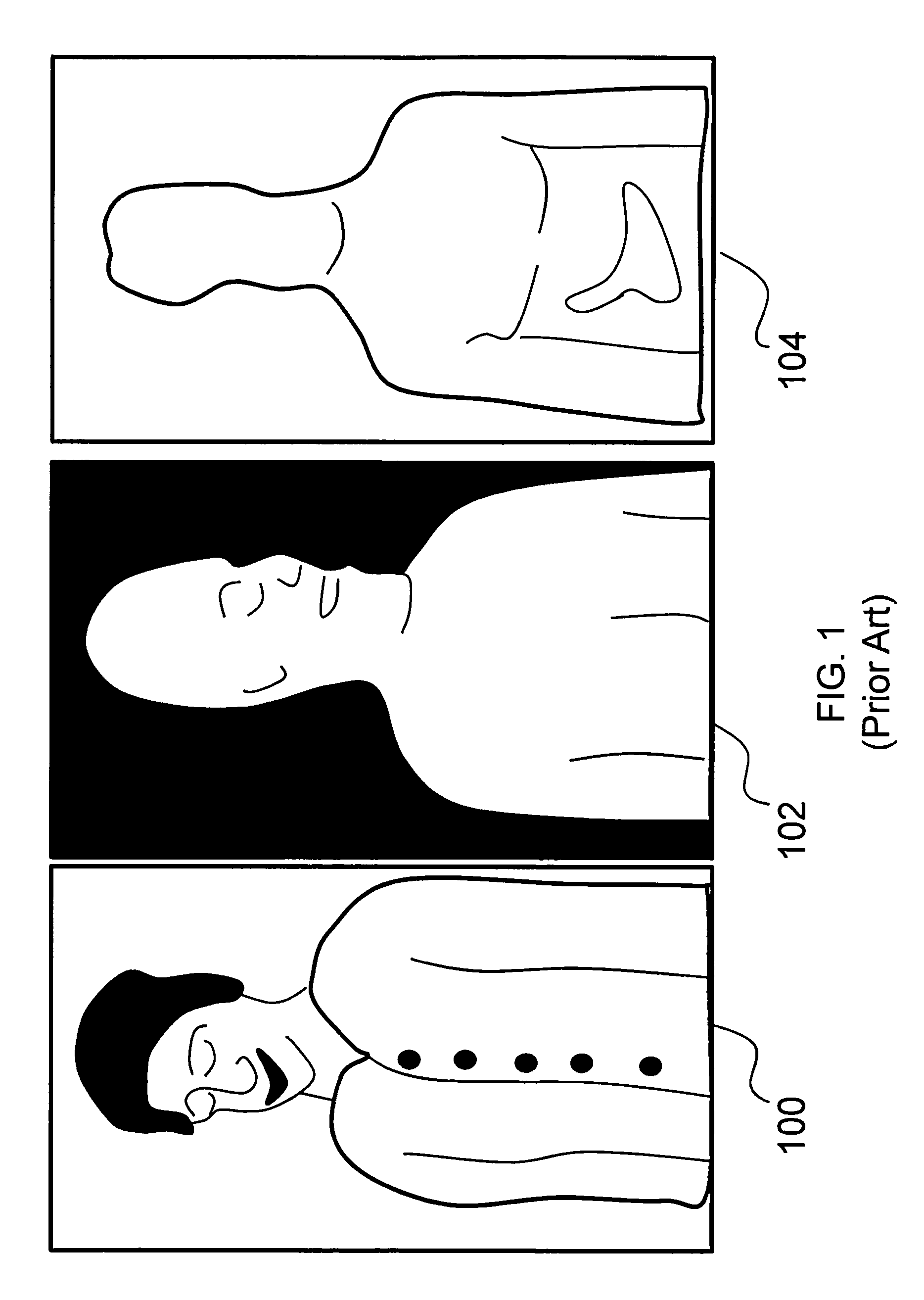
PRIORITY CLAIM[0001]The present application is a Continuation-in-Part application, claiming the benefit of priority of U.S. patent application Ser. No. 12 / 072,697, filed on Feb. 26, 2008, entitled, “System for anomaly detection using sub-space analysis.”FIELD OF INVENTION[0002]The present invention relates to an object detection and localization system and, more particularly, to a system that localizes and detects an object based on the shape of the object.BACKGROUND OF INVENTION[0003]The security industry is in need of technological innovation for producing automated image analysis systems for detecting concealed objects underneath a person's clothing. As shown in FIG. 1, existing imaging modalities include a visible image 100, a millimeter wave image (mmW) 102, and backscatter X-ray image 104. The objective in such a system is to automate the process so that a human operator is not required to look at raw data. However, as shown, a visible image 100 does not identify concealed obj...

Claims


Application Information

Patent Timeline
IPC IPC(8): G06K9/62G06K9/00G06K9/48G06V10/764
CPCG06K9/00288G06K9/6284G06T7/0004G06T7/0085G06K9/6247G06K2209/09G06T2207/30112G06T2207/10116G06T7/13G06V40/172G06V2201/05G06V10/764G06V10/7715G06F18/2433G06F18/2135
Inventor SAISAN, PAYAM
Owner HRL LAB
Learn More