
Timepiece dial, method of manufacturing a timepiece dial, and a timepiece

a manufacturing method and dial technology, applied in the field of timepiece dials, can solve the problems of low dial production efficiency, metal foil is easily wrinkled, lack of luxury and attractive appearance of plastic, etc., and achieve the effect of outstanding appearance and electromagnetic wave transparency

Active Publication Date: 2013-04-23
SEIKO EPSON CORP
View PDF6 Cites 0 Cited by
  • Summary
  • Abstract
  • Description
  • Claims
  • Application Information

AI Technical Summary

Benefits of technology

[0039]This aspect of the invention enables appropriately using light passing the timepiece dial in a solar timepiece having the timepiece dial of the invention to produce power by means of a solar cell. In addition, while a solar cell disposed on the back side of the dial in a conventional timepiece adversely affects the overall appearance of the timepiece, a timepiece according to the invention having a solar cell disposed behind the timepiece dial can be rendered with a sufficiently pleasing appearance overall. More specifically, the effect of the invention is even more pronounced when used in a timepiece that has a solar cell disposed on the back side of the timepiece dial.
[0040]The invention can provide a timepiece dial having outstanding transparency to electromagnetic waves (radio and light) and an outstanding appearance, provide a timepiece dial manufacturing method that enables suitably manufacturing the timepiece dial, and provide a timepiece having the timepiece dial.

Problems solved by technology

Compared with metals such as Au and Ag, however, plastic lacks a sense of luxury and an attractive appearance.
A problem with this method, however, is that the metal foil is easily wrinkled when the foil is applied to the substrate.
Preventing such wrinkles requires extreme care in the bonding process, resulting in extremely low productivity in dial manufacture.
Furthermore, even when extreme care is used in the bonding process, completely preventing the creation of relatively small wrinkles, for example, is difficult, and obtaining a sufficiently outstanding appearance in the finished dial is difficult.
Another problem with this method is that a relatively high percentage of the dials are determined to be no good, which is undesirable in terms of both production yield and resource conservation.
These problems are particularly severe when the metal foil is relatively thin (such as 10 μm or less).
Furthermore, when the metal foil is relatively thin (such as 10 μm or less), the foil tears easily during the adhesion process.
This is undesirable with respect to dial productivity, production cost, and resource conservation.
There have also been attempts to coat the entire surface of a substrate with a metal film using a vapor phase formation method to form a coating so thin that light passes through, but such extremely thin metal films cannot produce a metallic luster with a sufficiently luxurious appearance, and cannot produce an appearance with the quality desired for a dial or timepiece.
As described above, a balance between an excellent decorative appearance and excellent transmittance of electromagnetic waves is therefore also needed in the dials used in such timepieces, but achieving both characteristics is extremely difficult.

Method used


Image

  • Timepiece dial, method of manufacturing a timepiece dial, and a timepiece
  • Timepiece dial, method of manufacturing a timepiece dial, and a timepiece
  • Timepiece dial, method of manufacturing a timepiece dial, and a timepiece

Examples


examples

[0137]Specific examples of the invention are described below.

[0138]1. Manufacturing a Timepiece Dial

[0139]Using the methods described below, 100 timepiece dials were manufactured as embodiments of the invention and 100 timepiece dials were manufactured as comparison samples.

embodiment 1

[0140]A substrate with the shape of a timepiece dial was manufactured from polycarbonate by compression molding, and was then cut and polished as needed. The resulting substrate was substantially round with an approximately 27 mm diameter and approximately 0.5 mm thickness (substrate preparation process). The maximum peak-valley height Ry of the substrate surface is ≦100 μm and was ≦2 μm. In addition, the surface roughness Rz of the substrate surface is ≦20 μm and was ≦0.3 μm.

[0141]This substrate is then cleaned. The substrate was cleaned by dipping in an alkaline degreasing solution for 30 seconds followed by neutralization for 10 seconds, a water wash for 10 seconds, and a demineralized water wash for 10 seconds.

[0142]A dispersion containing Al powder (metal powder) with square particles when seen in plan view was then formed three times on one side of the cleaned substrate by spray coating (dispersion application process).

[0143]Spray coating was performed to apply the dispersion ...

embodiments 2 to 10

[0147]Timepiece dials were manufactured in the same way as in embodiment 1 except for changing the composition of the dispersion used to make the dispersion film, the composition of the substrate, and the conditions of the dispersion application process and heat process as shown in Table 1.


PUM


Abstract

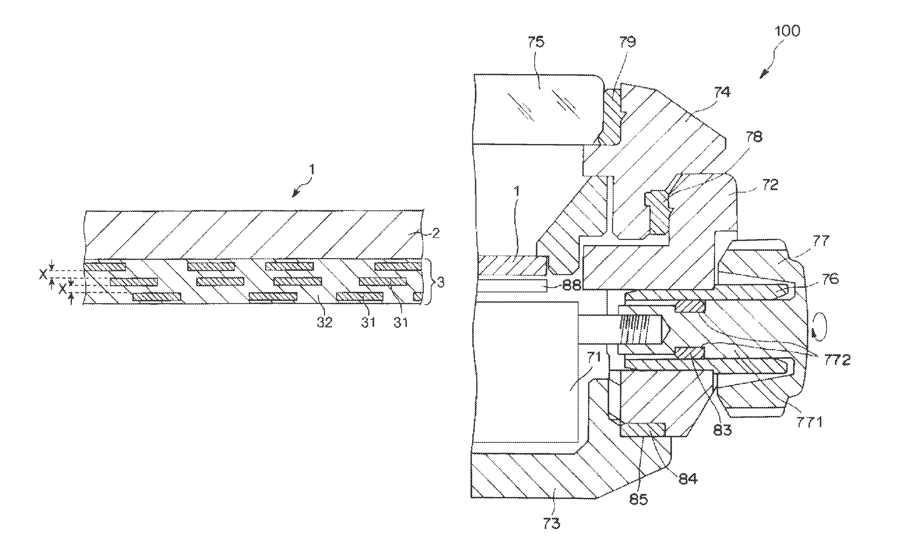
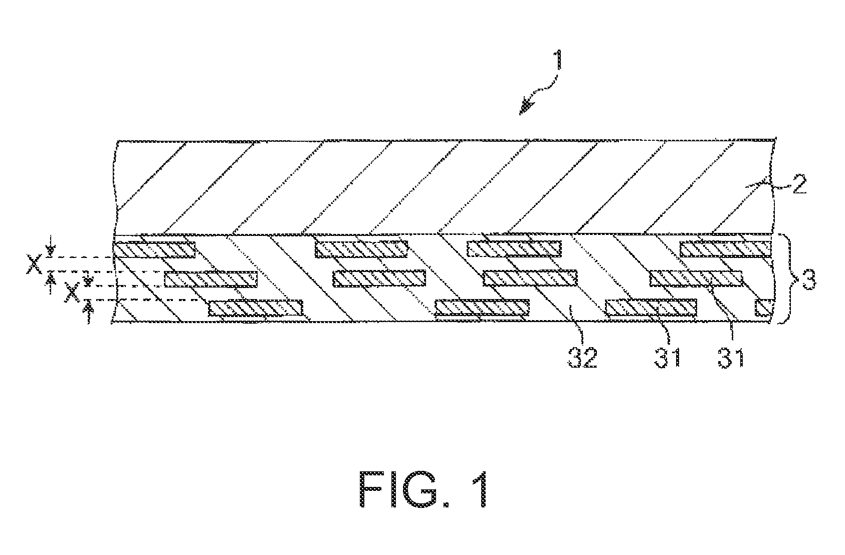
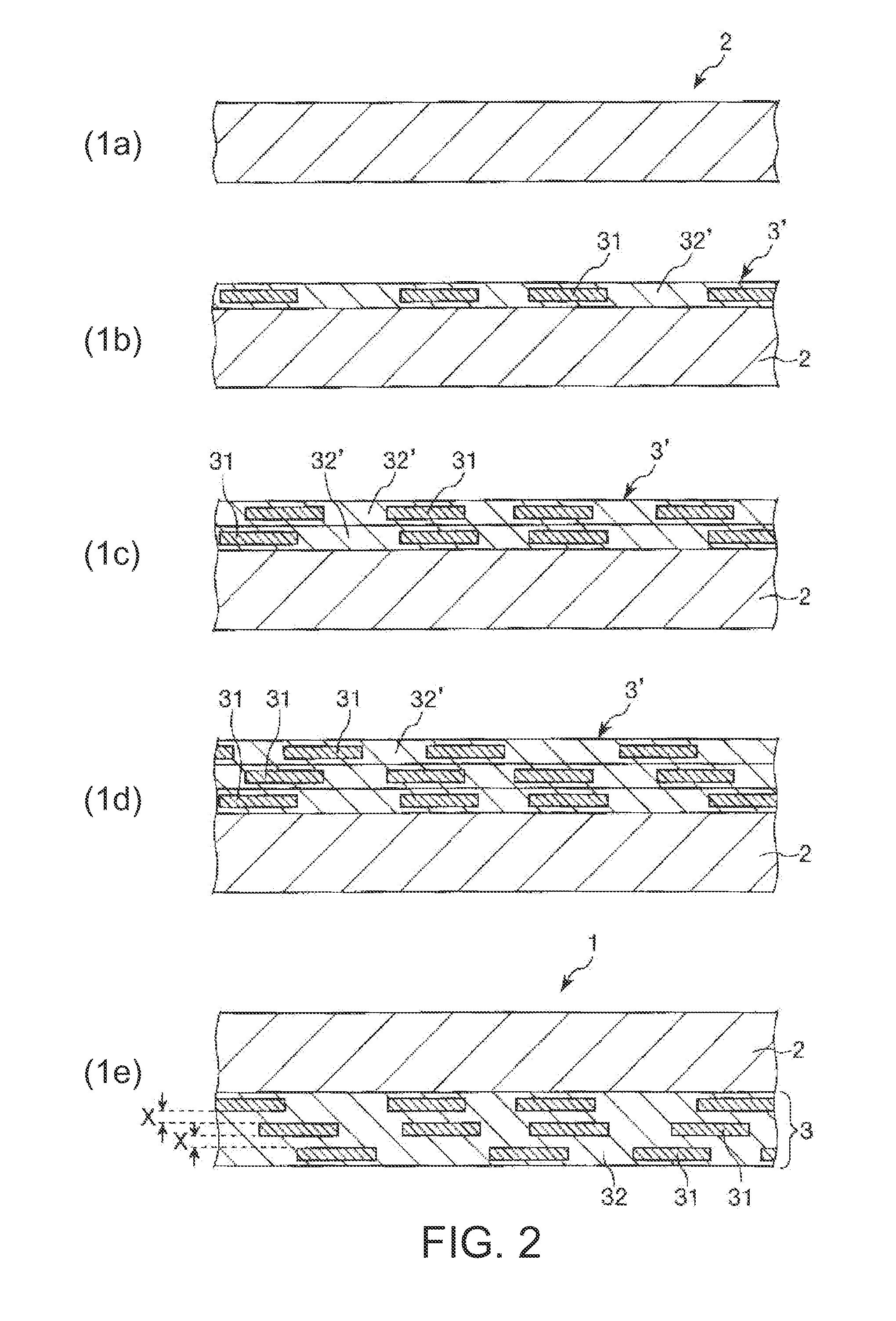
A timepiece dial has excellent transparency to electromagnetic waves (radio and light), and an excellent appearance, a timepiece dial manufacturing method enables manufacturing the timepiece dial, and a timepiece has the timepiece dial. The timepiece dial 1 has a substrate 2 that is electromagnetically transparent, and a dispersion film 3 containing a dispersion of metal powder 31 with an average particle diameter of 5 μm≦20 μm and an average particle thickness of 30 nm≦50 nm. The average thickness of the dispersion film 3 is 0.5 μm≦3.0 μm. The metal powder 31 is disposed with a specific gap therebetween in the through-thickness direction of the dispersion film 3.

Description

BACKGROUND[0001]1. Technical Field[0002]The present invention relates to a timepiece dial, a method of manufacturing a timepiece dial, and a timepiece.[0003]2. Related Art[0004]Dials used in solar timepieces (timepieces that have a photovoltaic cell) must have the ability (light transparency) to pass enough light for the solar cell to produce enough electromotive force (emf) for timepiece operations. Plastic parts with excellent transparency have therefore generally been used for dials in solar timepieces. Compared with metals such as Au and Ag, however, plastic lacks a sense of luxury and an attractive appearance. A dial that is manufactured by bonding metal foil with a hole therein to a plastic substrate by means of an adhesive attempts to solve this problem as taught in Japanese Unexamined Patent Appl. Pub. JP-A-11-326549 (particularly from line 35, right column, page 3 to line 11, left column, page 4).[0005]A problem with this method, however, is that the metal foil is easily wr...

Claims


Application Information

Patent Timeline
Patent Type & Authority Patents(United States)
IPC IPC(8): G04B19/06
CPCG04C10/02G04B19/12
Inventor TAKASAWA, KOKI
Owner SEIKO EPSON CORP
Learn More