
Multiple tile output using interface compression in a raster stage

a raster stage and interface compression technology, applied in the field of hardware accelerated graphics computer systems, can solve the problems of increasing clock speed, unable to scale up the prior art 3-d rendering architecture to handle the increasingly complex 3-d scenes of today's applications, and increasing so as to reduce the performance of the raster stage is dramatically increased, and the effect of reducing the amount of silicon die area

Active Publication Date: 2013-04-23
NVIDIA CORP
View PDF163 Cites 16 Cited by
  • Summary
  • Abstract
  • Description
  • Claims
  • Application Information

AI Technical Summary

Benefits of technology

The present invention provides a method and system for a rasterization process that can adapt to the needs of graphics applications without increasing power consumption or reducing production yield. Specifically, the interface compression method allows for a reduction in silicon die area, allowing for increased performance without unnecessary bloat in interfaces between components. This results in a scalable raster stage that can meet the needs of larger graphics applications.

Problems solved by technology

A problem exists however with the ability of prior art 3-D rendering architectures to scale to handle the increasingly complex 3-D scenes of today's applications.
Traditional methods of increasing 3-D rendering performance, such as, for example, increasing clock speed, have negative side effects such as increasing power consumption and increasing the heat produced by the GPU integrated circuit die.
Other methods for increasing performance, such as incorporating large numbers of parallel execution units for parallel execution of GPU operations have negative side effects such as increasing integrated circuit die size, decreasing yield of the GPU manufacturing process, increasing power requirements, and the like.

Method used


Image

  • Multiple tile output using interface compression in a raster stage
  • Multiple tile output using interface compression in a raster stage
  • Multiple tile output using interface compression in a raster stage

Examples


Embodiment Construction

[0022]Reference will now be made in detail to the preferred embodiments of the present invention, examples of which are illustrated in the accompanying drawings. While the invention will be described in conjunction with the preferred embodiments, it will be understood that they are not intended to limit the invention to these embodiments. On the contrary, the invention is intended to cover alternatives, modifications and equivalents, which may be included within the spirit and scope of the invention as defined by the appended claims. Furthermore, in the following detailed description of embodiments of the present invention, numerous specific details are set forth in order to provide a thorough understanding of the present invention. However, it will be recognized by one of ordinary skill in the art that the present invention may be practiced without these specific details. In other instances, well-known methods, procedures, components, and circuits have not been described in detail ...


PUM


Abstract

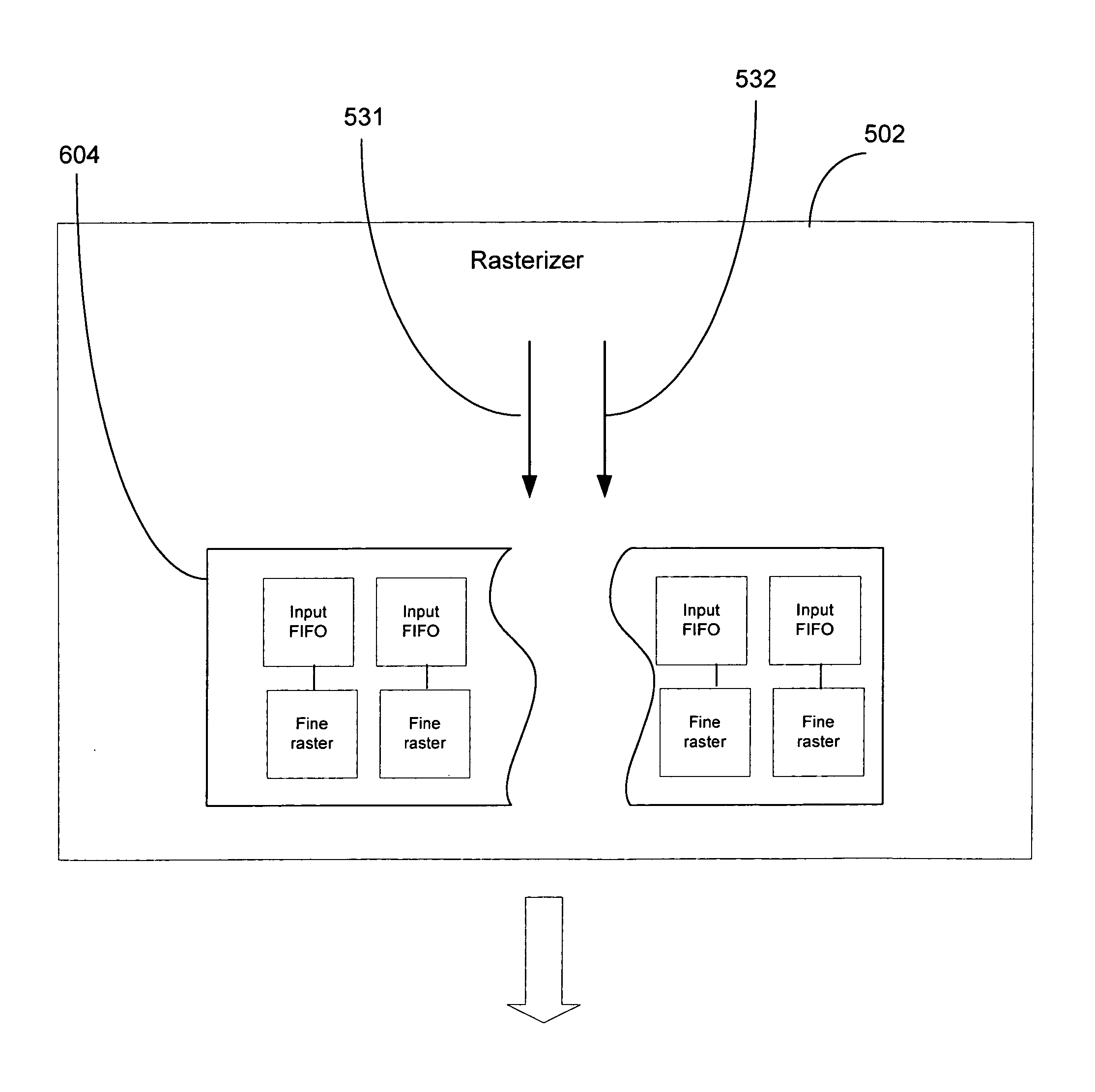
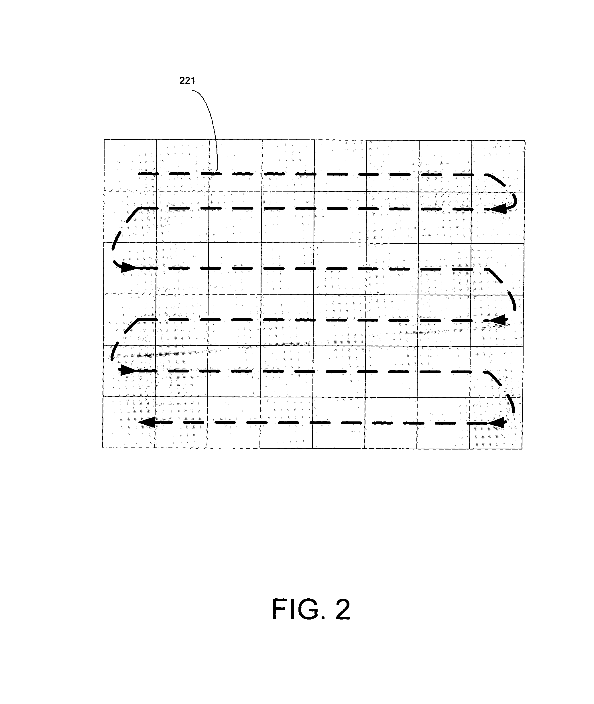
A method and system for interface compression in a raster stage of a graphics processor. The method includes receiving a graphics primitive for rasterization in a raster stage of a graphics processor and rasterizing the graphics primitive at a first level in a coarse raster component to generate a plurality of tiles related to the graphics primitive. The method determines whether a window ID operation is required for the plurality of tiles. If the operation is required, a respective plurality of uncompressed coverage masks for the tiles are output from the coarse raster component to a fine raster component on a one coverage mask per clock cycle basis. If the operation is not required, a compressed coverage mask for the tiles is output in a single clock cycle. The tiles are subsequently rasterized at a second-level in the fine raster component to generate pixels related to the graphics primitive.

Description

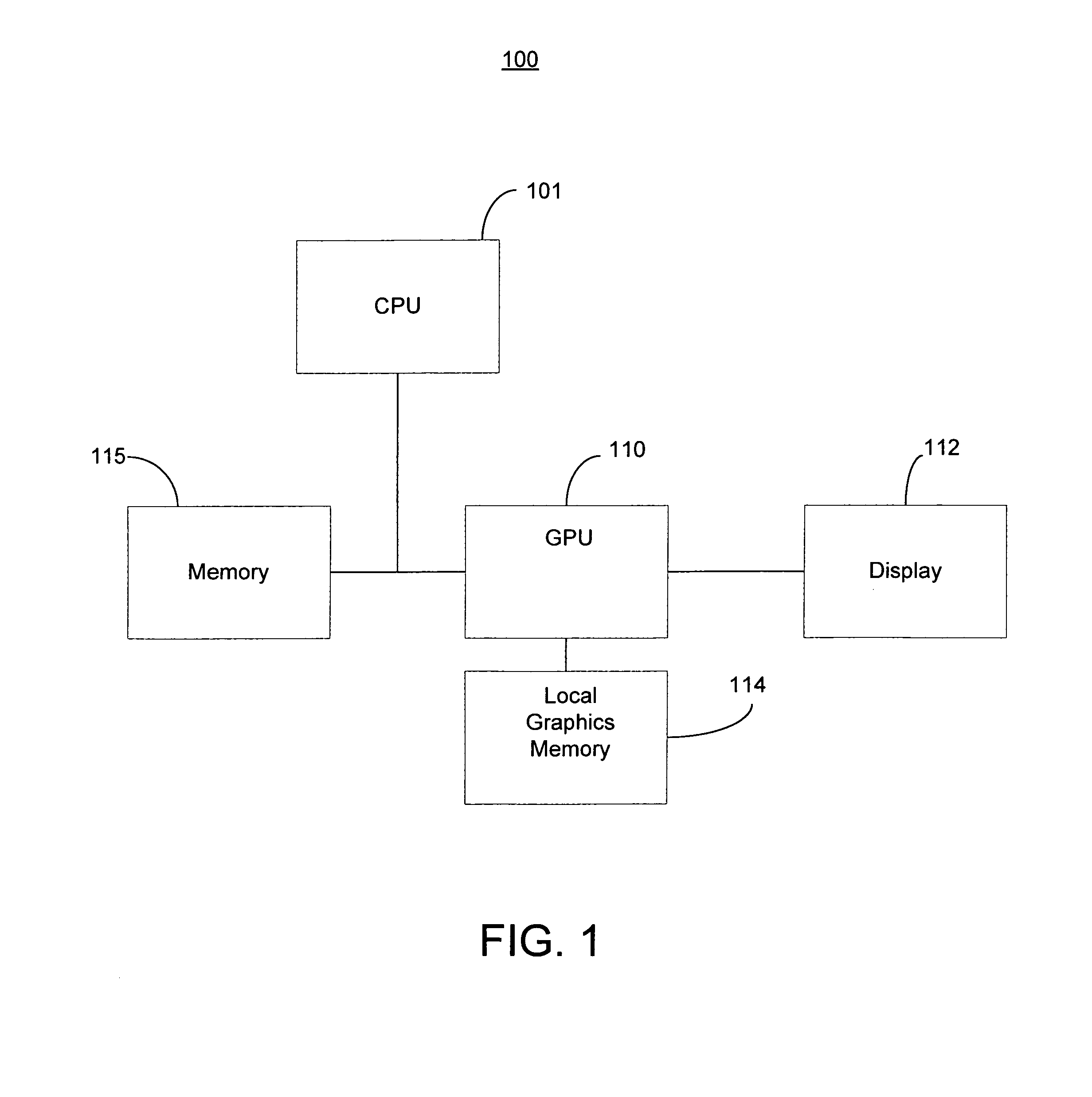
FIELD OF THE INVENTION[0001]The present invention is generally related to hardware accelerated graphics computer systems.BACKGROUND OF THE INVENTION[0002]Recent advances in computer performance have enabled graphic systems to provide more realistic graphical images using personal computers, home video game computers, handheld devices, and the like. In such graphic systems, a number of procedures are executed to “render” or draw graphic primitives to the screen of the system. A “graphic primitive” is a basic component of a graphic picture, such as a point, line, polygon, or the like. Rendered images are formed with combinations of these graphic primitives. Many procedures may be utilized to perform 3-D graphics rendering.[0003]Specialized graphics processing units (e.g., GPUs, etc.) have been developed to optimize the computations required in executing the graphics rendering procedures. The GPUs are configured for high-speed operation and typically incorporate one or more rendering p...

Claims


Application Information

Patent Timeline
IPC IPC(8): G06T1/20
CPCG06T11/40
Inventor CROW, FRANKLIN C.
Owner NVIDIA CORP
Learn More