
Plate heat exchanger having a turbulence generator

a technology of turbulence generator and plate heat exchanger, which is applied in the direction of heat transfer modification, lighting and heating apparatus, laminated elements, etc., can solve the problems of different individual turbulence generators that have to be manufactured, turbulence generators that do not in every instance guarantee optimum heat transfer, and cannot ensure optimum heat transfer

Active Publication Date: 2013-04-16
MAHLE INT GMBH
View PDF37 Cites 16 Cited by
  • Summary
  • Abstract
  • Description
  • Claims
  • Application Information

AI Technical Summary

Benefits of technology

This patent aims to improve the heat transfer of a plate heat exchanger by making the elevations and depressions of at least one row flat-topped and parallel to the neighboring separating wall. The bridges of each row are made equal and inclined relative to the separating walls, leading to good mixing and heat transfer. A low-cost rolling-stamping process is used, followed by a planishing tool to adapt the height of the turbulence generator and horizontal shift of the elevations to the distance of the separating walls. This process wides the openings between the individual rows. The height of the turbulence generator can be adapted to different applications, optimizing heat transfer performance and reducing pressure drop.

Problems solved by technology

It is disadvantageous that different individual turbulence generators have to be manufactured for heat exchangers having different distances between the separating walls.
Furthermore it has been found that these known turbulence generators do not in every instance guarantee optimum heat transfer.
Such profile elements will not ensure optimum heat transfer.

Method used


Image

  • Plate heat exchanger having a turbulence generator
  • Plate heat exchanger having a turbulence generator
  • Plate heat exchanger having a turbulence generator

Examples


Embodiment Construction

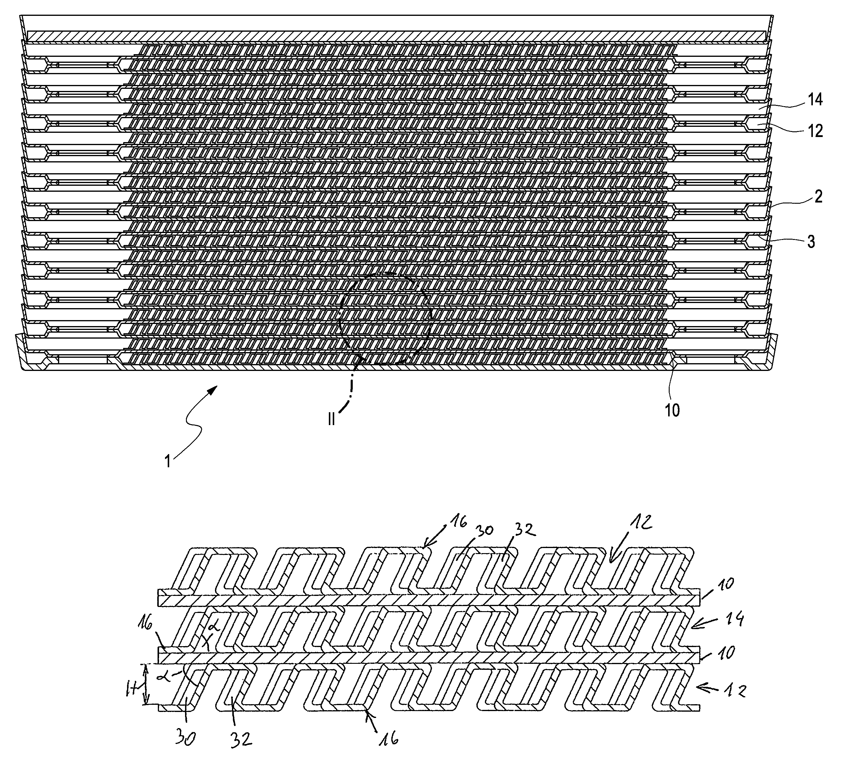
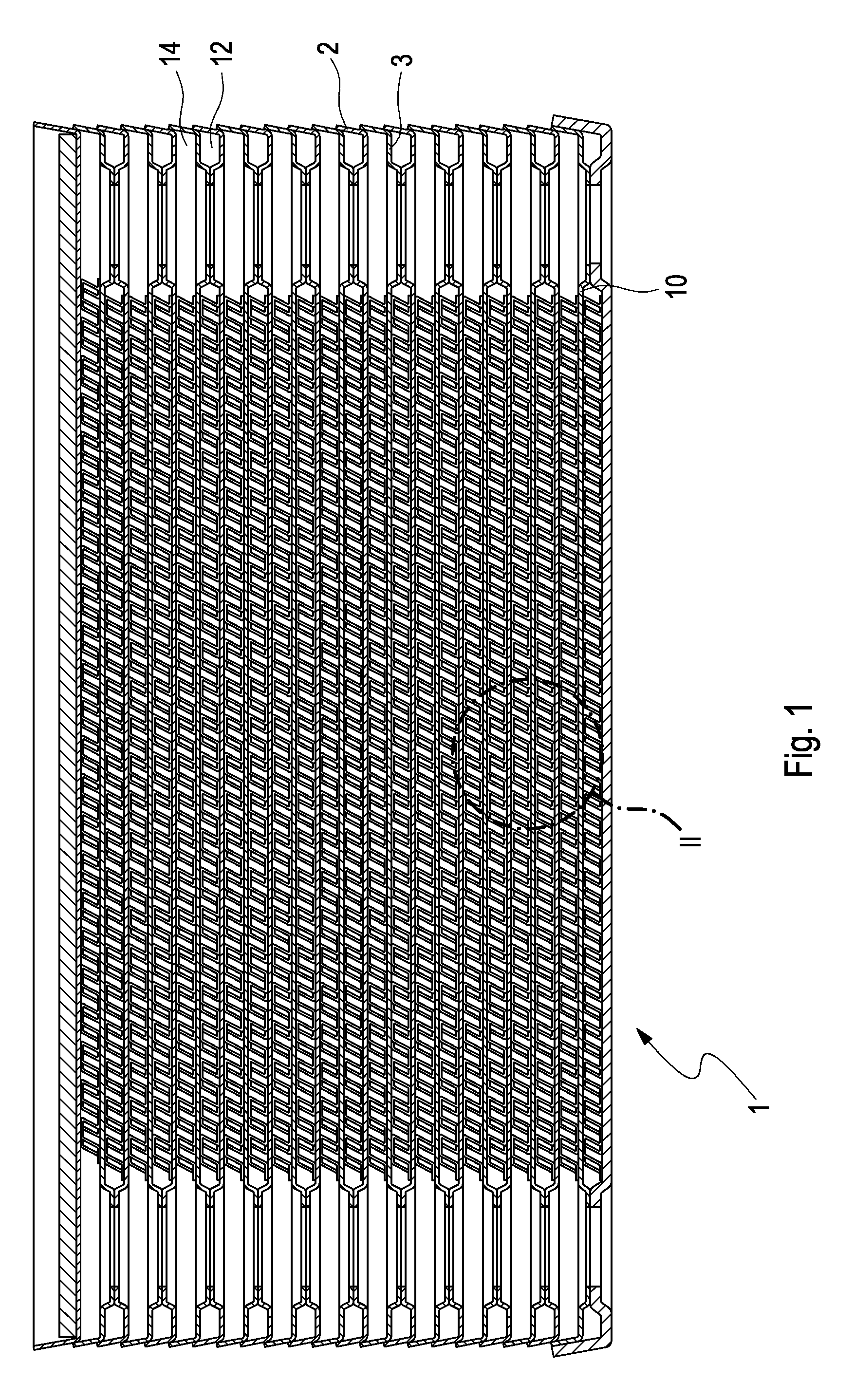
[0033]The plate heat exchanger 1 consists of a stack 2 of deep-drawn, trough-shaped sheet iron plates 3, the sheet iron plates 3 forming parallel, distanced separating walls 10. The separating walls 10 alternatingly define a first flow space 12 for a first medium and a second flow space 14 for a second medium. The first medium may for instance be oil, which is to be cooled, the second medium may be a coolant, e.g. water.

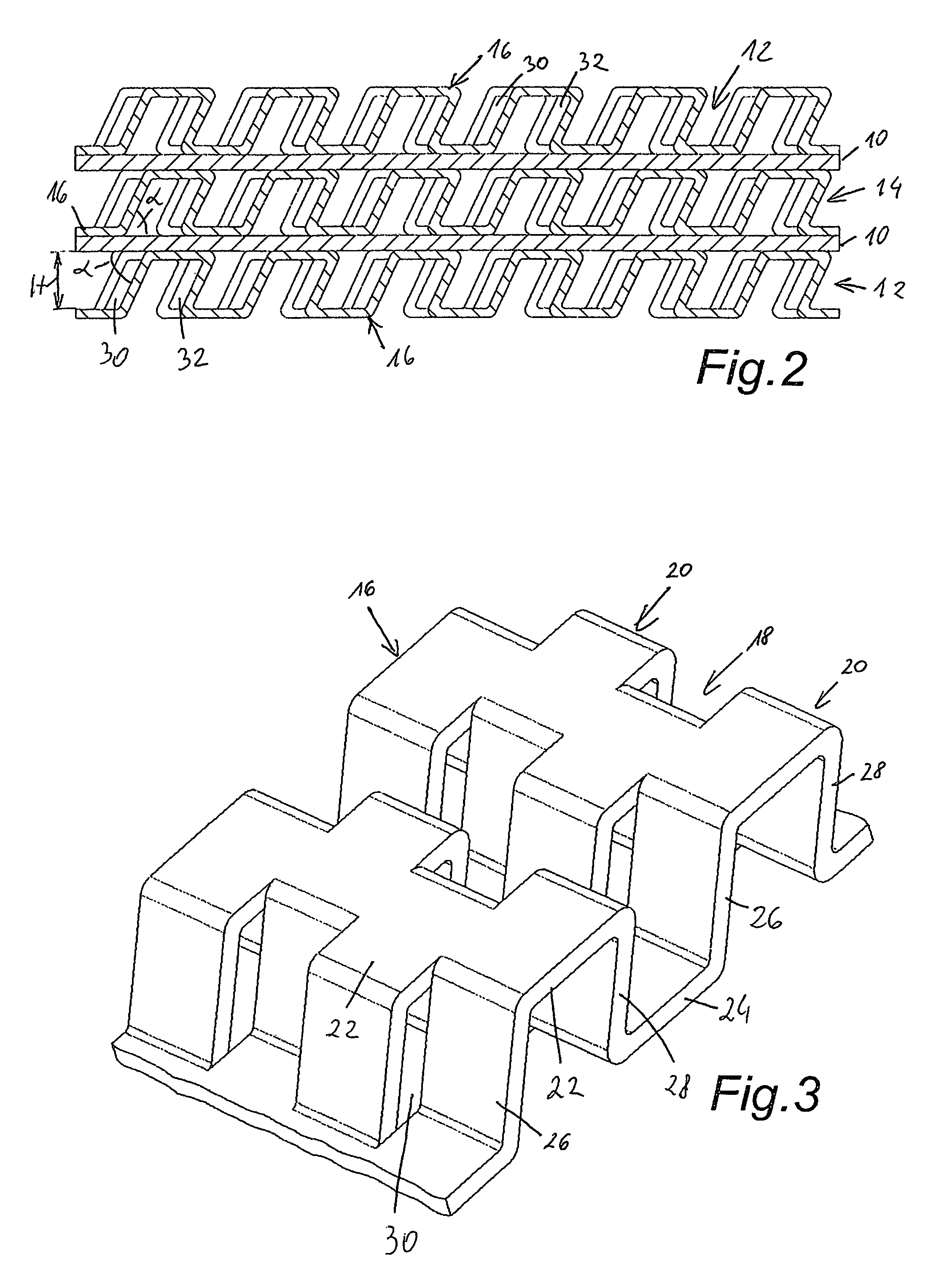
[0034]In the embodiment shown plate-shaped turbulence generators 16 are provided in the first flow space 12 as well as in the second flow space 14. Each turbulence generator 16 has a plurality of band-shaped rows 18, 20 lying side by side and having elevations 22 and depressions 24. The elevations 22 are linked to the depressions 24 by bridges 26, 28. Two immediately adjacent rows are shifted against each other, that is, elevations 22 and depressions 24 of one row 18 are staggered relative to those of each immediately adjacent row 20, 18. Each row 18 thus has a trans...


PUM

PropertyMeasurementUnit
angleaaaaaaaaaa
angleaaaaaaaaaa
angleaaaaaaaaaa

Abstract

A plate heat exchanger with a plurality of separating walls stacked one above the other, which alternatingly define a first and second flow space for a first and second medium, includes at least one turbulence generator being positioned in at least one flow space, which comprises a plate with a number of parallel-running band-like rows of alternating elevations and depressions mutually connected by bridges, where the elevations and depressions of each row are shifted with respect to each immediately adjacent row, and where each row is provided with at least one transition area for the medium to pass to the immediately adjacent row, such that the depressions of each row are flow-connected with the immediately adjacent elevations of at least one immediately adjacent row. To achieve high heat transfer performance in a simple manner it is provided that the bridges of each row are essentially parallel and equally inclined relative to the separating walls, with an acute angle being formed between a separating wall and the bridges.

Description

BACKGROUND OF THE INVENTION[0001]The invention relates to a plate heat exchanger with a plurality of separating walls stacked one above the other, which alternatingly define a first and second flow space for a first and second medium, a turbulence generator preferably made of sheet metal being positioned in at least one flow space, which generator comprises a plate with a number of parallel-running band-like rows of alternating elevations and depressions mutually connected by bridges, where the elevations and depressions of one row are shifted with respect to the immediately adjacent row, and where each row is provided with at least one transition area for the medium to pass to the immediately adjacent row, such that the depressions of each row are flow-connected with the immediately adjacent elevations of at least one immediately adjacent row.[0002]Plate heat exchangers, especially oil / water heat exchangers consist of a plurality of plates stacked one above the other, forming alter...

Claims


Application Information

Patent Timeline
Patent Type & Authority Patents(United States)
IPC IPC(8): F28F13/12F28F3/00
CPCB21D53/02F28F13/12F28F3/027Y10T29/4935
Inventor OTAHAL, KLAUSHOFER, JOSEF
Owner MAHLE INT GMBH
Learn More