
Protective head having impact force distribution

a head and impact force technology, applied in the field of protective head gear, can solve the problems of traumatic brain injury, severe head injury, and severe head injury, and achieve the effects of dispersing built up heat, reducing the kinetic energy absorption of present invention, and reducing the risk of brain injury

Inactive Publication Date: 2013-04-16
MCBRIDE WILLIAM B
View PDF6 Cites 24 Cited by
  • Summary
  • Abstract
  • Description
  • Claims
  • Application Information

AI Technical Summary

Benefits of technology

The invention provides a protective helmet that has the same ballistic stopping power as current helmets but also helps absorb the energy when a bullet or fragment impacts the helmet. The helmet has an active cooling system to help dissipate built-up heat, which is important because helmets typically get hot when used. The helmet is lightweight and can be configured in a normal way.

Problems solved by technology

These materials offer excellent bullet and fragmentation stopping power although most helmets are unable to stop a direct hit from a high caliber high velocity round.
Although the ballistic outer shell may save the soldier's life, severe injury may occur when a bullet or shrapnel hits the helmet causing the wearer traumatic brain injury.
Such traumatic brain injuries may have drastic and long-term negative effects on the sufferer.
So while the helmet prevents the bullet or fragment from directly contacting and penetrating the user's head, the incoming round or fragment has a tremendous amount of kinetic energy that is absorbed by the outer shell and transferred to the user's head resulting in a localized and often severe injury to the head at the area of impact.
While such a cushioning layer helps reduce the injury caused from a bullet or fragment impact with the outer shell, the potential for serious injury remains due to the fact that the cushioning layer can dissipate only a certain amount of energy for a given amount of cushioning material.
All these requirements make the design of a modern helmet one of tradeoffs and compromises.
Such heat can dramatically diminish the cognitive functioning of the solder and thus his or her combat effectiveness.

Method used


Image

  • Protective head having impact force distribution
  • Protective head having impact force distribution
  • Protective head having impact force distribution

Examples


Embodiment Construction

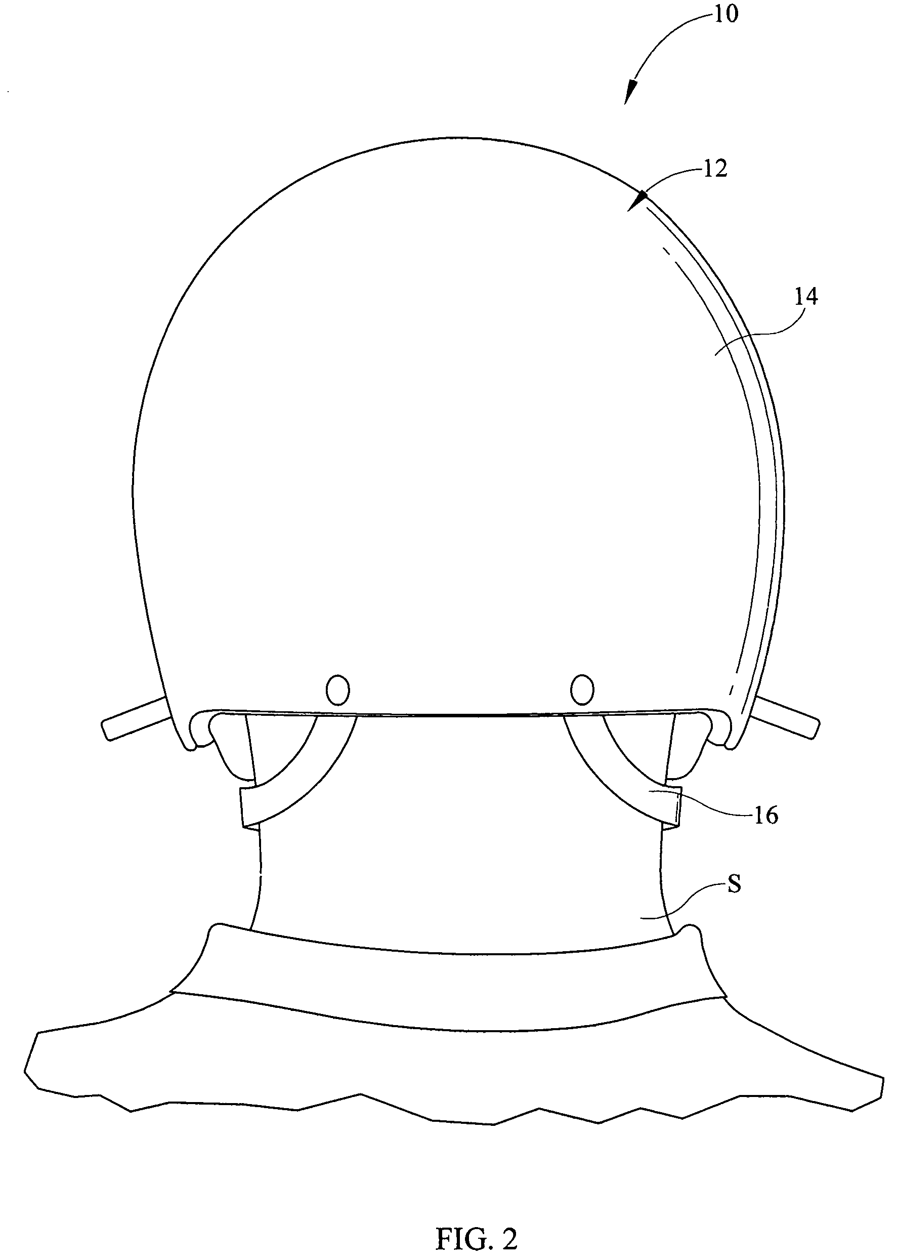
[0015]Referring now to the drawings, it is seen that the protective head gear having impact force distribution of the present invention, generally denoted by reference numeral 10, is comprised of an overall helmet body 12 that has an outer shell 14 that is made from an appropriate ballistic material such as Kevlar, Aramid, Ultra high molecular weight polyethylene (UHMWPE, sold under the trade names Dyneema and Spectra), etc. The shape of the helmet body 12 is based on the needs of the end user. For example, the US Army may desire a relatively high cut back portion of the helmet body 12 in order for the helmet 10 to cooperate with the Army's Improved Outer Tactical Vest currently in use. As seen, appropriate strapping 16 is attached to the helmet body 12 in usual fashion, the specific design of the strapping 16 being end-user defined. As seen, an opening 18 is present on each side of the helmet body 12 which coincides with each ear E of the user S. Appropriate attachment brackets 22 ...


PUM

PropertyMeasurementUnit
threshold decibel levelaaaaaaaaaa
frequencyaaaaaaaaaa
areaaaaaaaaaaa

Abstract

A helmet that protects a user's head from the transfer of force imparted on the outer shell of the helmet. An inner layer of the helmet uses a spacer fabric that diffuses any force received over a relatively large area so that such force is spread over a relatively large area of the user's head, thereby reducing the risk of traumatic brain injury. The helmet uses a thermal pack that helps keep the user either cold or hot as desired. The helmet uses an audio pack that is removably attached to the shell, such that the audio pack protects the hearing of the user from sudden high decibel sounds and also amplifies desirable sound while squelching undesirable noise.

Description

BACKGROUND OF THE INVENTION[0001]1. Field of the Invention[0002]The present invention relates to protective head gear, namely a helmet, wherein the helmet distributes a localized impact force across a much larger area relative to area of impact.[0003]2. Background of the Prior Art[0004]The combat helmet is a type of personal protection worn by a soldier during combat. It is one of the oldest forms of personal armor, having been known to be worn by the Assyrians as far back as 900 BC. The modern helmet is typically formed as an outer shell made from a ballistic material such as Kevlar or Aramid. These materials offer excellent bullet and fragmentation stopping power although most helmets are unable to stop a direct hit from a high caliber high velocity round. Although the ballistic outer shell may save the soldier's life, severe injury may occur when a bullet or shrapnel hits the helmet causing the wearer traumatic brain injury. Such traumatic brain injuries may have drastic and long...

Claims


Application Information

Patent Timeline
Patent Type & Authority Patents(United States)
IPC IPC(8): A41B1/06A63B71/10
CPCA42B3/285F41H1/08A42B3/30
Inventor MCBRIDE, WILLIAM B.
Owner MCBRIDE WILLIAM B
Learn More