Power subassembly for micro-hybrid system in an automobile

a micro-hybrid system and power sub-assembly technology, applied in the direction of electric vehicles, battery/fuel cell control arrangements, electric devices, etc., can solve the problems of increasing the difficulty of car manufacturers incorporating new systems, the length of branching cables which form the power bus can be substantial, and the element can be relatively bulky, so as to reduce the parasitic inductance, reduce the design stress, and the effect of simple connection

Active Publication Date: 2013-04-09
VALEO EQUIP ELECTRIC MOTEUR
View PDF5 Cites 7 Cited by
  • Summary
  • Abstract
  • Description
  • Claims
  • Application Information

AI Technical Summary

Benefits of technology

[0015]This results in a reduction in the design stresses, in particular because the capacitor at the terminals of the AC-DC converter can retain a low value. In addition, this power bus enables a simple connection which is favourable for good reliability.
[0035]The cover comprises a polarising slot which advantageously makes it possible to avoid connection errors between the connection means, and thus to further increase the reliability of the power sub-assembly.

Problems solved by technology

However, the integration of this type of micro-hybrid system in the engine compartment of a modern motor vehicle may cause problems.
In fact, a micro-hybrid system consists of elements which must be interconnected with one another, some of these elements being able to be relatively bulky.
Since the engine compartment of a motor vehicle has a relatively limited amount of space, it is becoming increasingly difficult for car manufacturers to incorporate new systems into them.
Thus, the lengths of branching cables which form the power bus can be substantial, and introduce parasitic inductances of a type which is to the detriment of the micro-hybrid system in switched dynamic running conditions.
The power bus which is placed between the AC-CD converter of the micro-hybrid system and the energy storage device poses a particular problem.
The parasitic inductance of this power bus can firstly affect the energy performance at certain frequencies, and can also give rise to excess resonance voltages.
In addition, the parasitic inductance can affect adversely the electromagnetic compatibility.
The excess resonance voltages can give rise to uncontrolled avalanche phenomena in MOSFET power transistors of the AC-DC converter, these avalanche phenomena being able to detract from the functioning of these transistors, or damage them.
Since this capacitor must preferably be integrated in the AC-DC converter, there is an integration constraint which is difficult to fulfil because of the size of the capacitor.

Method used


Image

  • Power subassembly for micro-hybrid system in an automobile
  • Power subassembly for micro-hybrid system in an automobile
  • Power subassembly for micro-hybrid system in an automobile

Examples


first embodiment

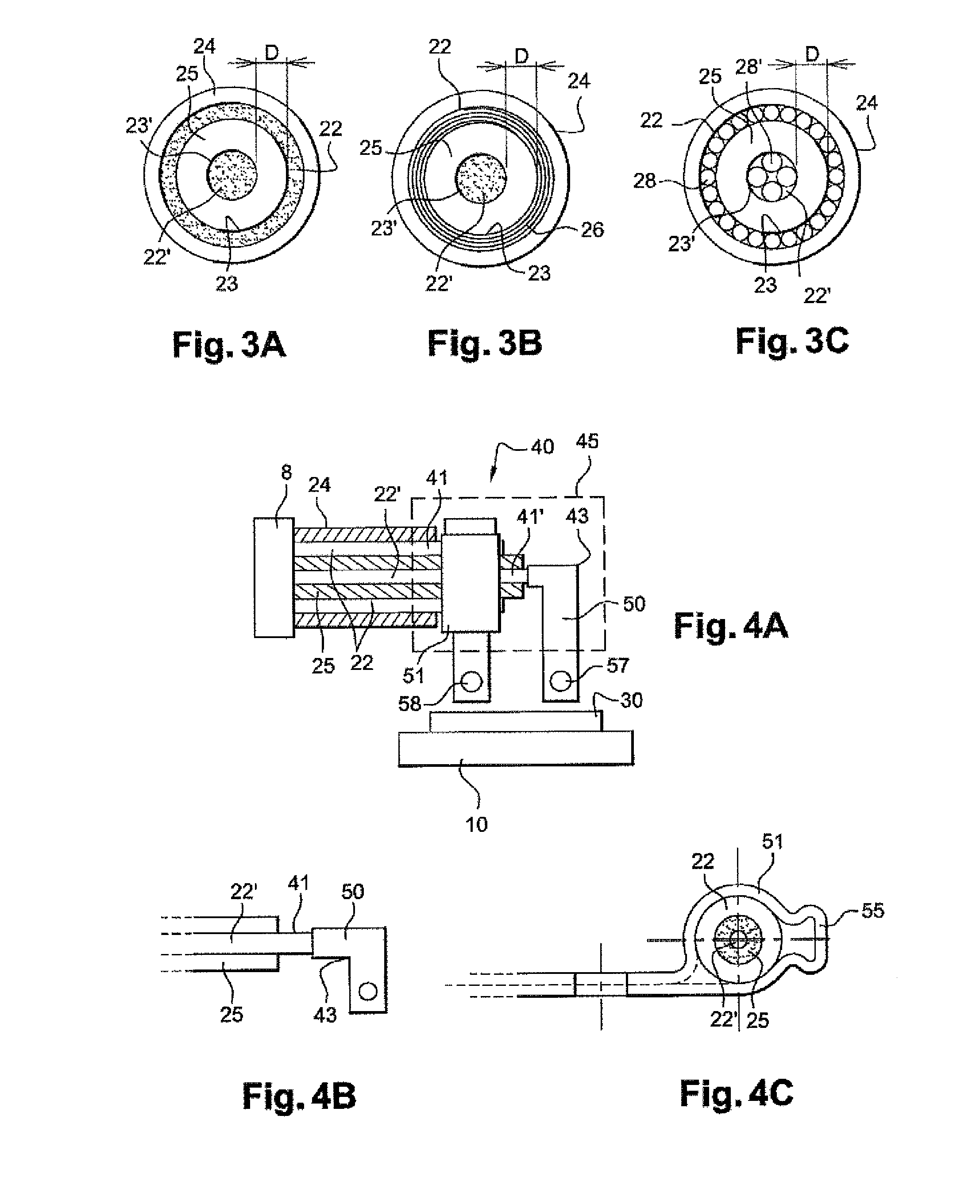
[0075]FIG. 3 shows a cross-section according to the section of the power bus 9. This power bus 9 comprises conductors 22, 22′ which are accommodated in a sheath 24 formed by insulation 25. The conductors 22, 22′ comprise respective coaxial cylindrical surfaces 23, 23′.

[0076]As shown in FIG. 3A, the two so-called coaxial conductors 22, 22′ form a conventional coaxial cable which has a central conductor 22′ with a circular cross-section. According to particular embodiments of the invention, and in accordance with its applications, a coaxial conductor 22 comprises a cross-section which varies between approximately 15 mm2 and approximately 50 mm2. The circular form of the conductors 22, 22′ permits improvement of the electromagnetic coupling, and enables an inductance value of between approximately 0.1 μH and approximately 1 μH.

[0077]In addition, the two coaxial conductors 22, 22′ in FIG. 3A are accommodated in a single sheath 24. This characteristic makes it possible to minimise the th...

second embodiment

[0078]FIG. 3B shows a cross-section according to the section of the power bus 9 according to the invention, again with coaxial conductors 22, 22′. In this embodiment, the coaxial cable 22 comprises a plurality of rolled metal sheets 26. In comparison with the embodiment which is illustrated in FIG. 3A, the characteristic of FIG. 3B permits an increase in the flexibility of the conductor 22. It will be appreciated that the conductor 22′ can also comprise a plurality of rolled metal sheets.

third embodiment

[0079]FIG. 3C shows a cross-section according to the section of the power bus 9. In this embodiment, the conductors 22, 22′ comprise metal braids which are formed by a plurality of wires with a small cross-section 28, 28′. The metal braids comprise substantially cylindrical coaxial surfaces 23, 23′ which have the same function as the cylindrical coaxial surface previously described with reference to FIG. 3A. This embodiment has the advantage of using low-cost conductors.

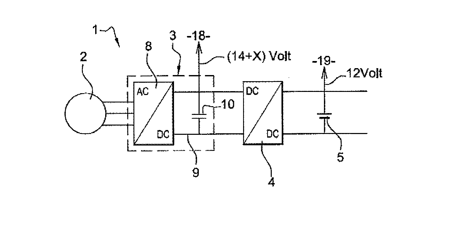
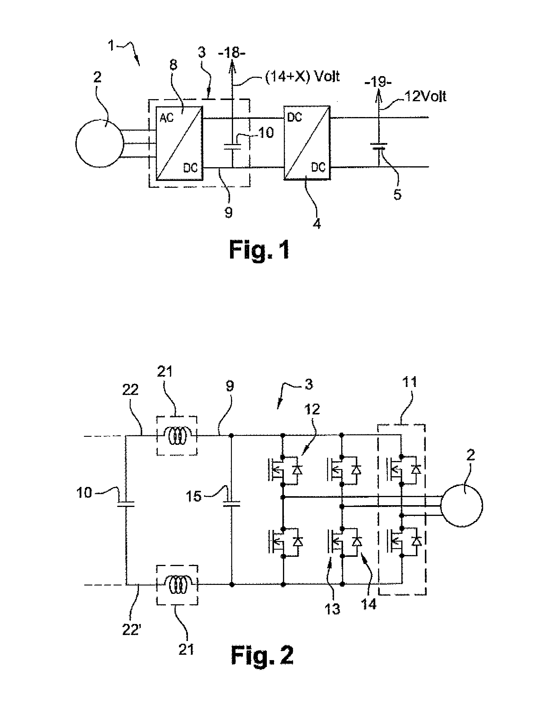
[0080]The power bus 9 according to the invention guarantees the reliability of the micro-hybrid system 1. In fact, the characteristics of the conductors 22, 22′ according to the invention make it possible to limit the inductance 21, such as to avoid the excess voltages at the terminals of the transistors 13 of the AC / DC converter 8, and the resulting avalanche phenomena. A power bus 9 according to the invention permits efficient transfer of energy between the storage means 5 and 10 and the alternator-starter 2, despi...


PUM


Abstract

According to the disclosure, a power sub-assembly (3) for a micro-hybrid system (1) in an automobile includes an AC-DC converter (8) with a transistor bridge (13), an energy storage device (10) and a power bus (9) including at least two cylindrical conductors (22, 22′). According to the disclosure, conductors (22, 22′) include respective coaxial cylindrical surfaces (23, 23′). The power bus integrated in the power subassembly allows for a parasitic inductance that is by far lower than that of the standard cables in power subassemblies of the prior art, particularly in order to avoid overvoltage at the terminals of the transistors in the AC-DC converter.

Description

FIELD OF THE INVENTION[0001]The present invention has applications in the motor vehicle field. More particularly, it relates to a power sub-assembly of a micro-hybrid system for a motor vehicle, comprising an AC-DC converter with a transistor bridge, an energy storage device, and a power bus.BACKGROUND OF THE INVENTION[0002]For some years, the demand for “clean” vehicles has tended to increase as a result of the needs firstly to reduce fuel consumption and secondly to limit pollution.[0003]In general, hybrid systems and micro-hybrid systems are being developed for the purpose of fulfilling the aforementioned needs.[0004]Micro-hybrid systems are known, for example, with recuperative braking, wherein an alternator is used to collect mechanical torque, thus giving rise to braking of the vehicle. The alternator converts this collected torque into electrical energy, in order to charge an energy storage device in the form for example of a pack of super-capacitors or a battery. This energy...

Claims


Application Information

Patent Timeline
Patent Type & Authority Patents(United States)
IPC IPC(8): B60L1/00
CPCB60L3/00B60L2210/30H02M7/003Y02T10/7241B60L58/00Y02T10/72
Inventor CHEMIN, MICHAELABADIA, ROGERGUERIN, FABIENMANDION, THIERRYRONDIER, PATRICKLEBOEUF, CEDRIC
Owner VALEO EQUIP ELECTRIC MOTEUR
Why Eureka
Try Eureka