
Methods of controlling components of blasting apparatuses, blasting apparatuses, and components thereof

a technology of blasting apparatus and control device, which is applied in the direction of lighting and heating apparatus, electric fuzes, instruments, etc., can solve the problems of increased safety concerns, loss of communication between blasting machine and detonator, and labour intensive process

Active Publication Date: 2013-03-12
ORICA EXPLOSIVES TECH PTY LTD
View PDF74 Cites 59 Cited by
  • Summary
  • Abstract
  • Description
  • Claims
  • Application Information

AI Technical Summary

Benefits of technology

The patent describes a method for synchronizing the timing of blasting components in a blasting system. The method involves receiving a calibration signal and delineating its oscillations to establish a time zero. At a later time, a command signal is received to fire the blasting components. Each blasting component waits for the next synchronized time zero and then counts down its programmed delay time to actuate the associated explosive charge at a desired time. The technical effect of this method is the achievement of a precise blasting pattern.

Problems solved by technology

The process is often labour intensive and highly dependent upon the accuracy and conscientiousness of the blast operator.
Inadequate connections between components of the blasting arrangement can lead to loss of communication between blasting machines and detonators, and therefore increased safety concerns.
However, such systems present formidable technological challenges, many of which remain unresolved.
One obstacle to automation is the difficulty of robotic manipulation and handling of blast apparatus components at the blast site, particularly where the components require tieing-in or other forms of hook up to electrical wires, shock tubes or the like.
Nonetheless, existing wireless blasting systems still present significant safety concerns, and improvements are required if wireless blasting systems are to become a more viable alternative to traditional “wired” blasting systems.

Method used


Image

  • Methods of controlling components of blasting apparatuses, blasting apparatuses, and components thereof
  • Methods of controlling components of blasting apparatuses, blasting apparatuses, and components thereof
  • Methods of controlling components of blasting apparatuses, blasting apparatuses, and components thereof

Examples


example 1

Method for Communication Between Components of a Blasting Apparatus

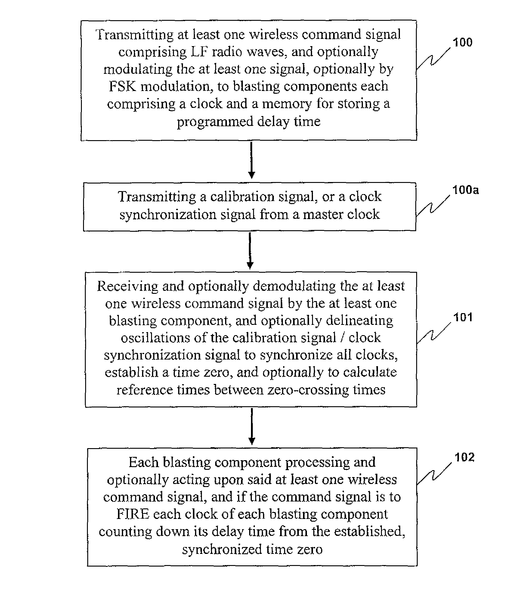
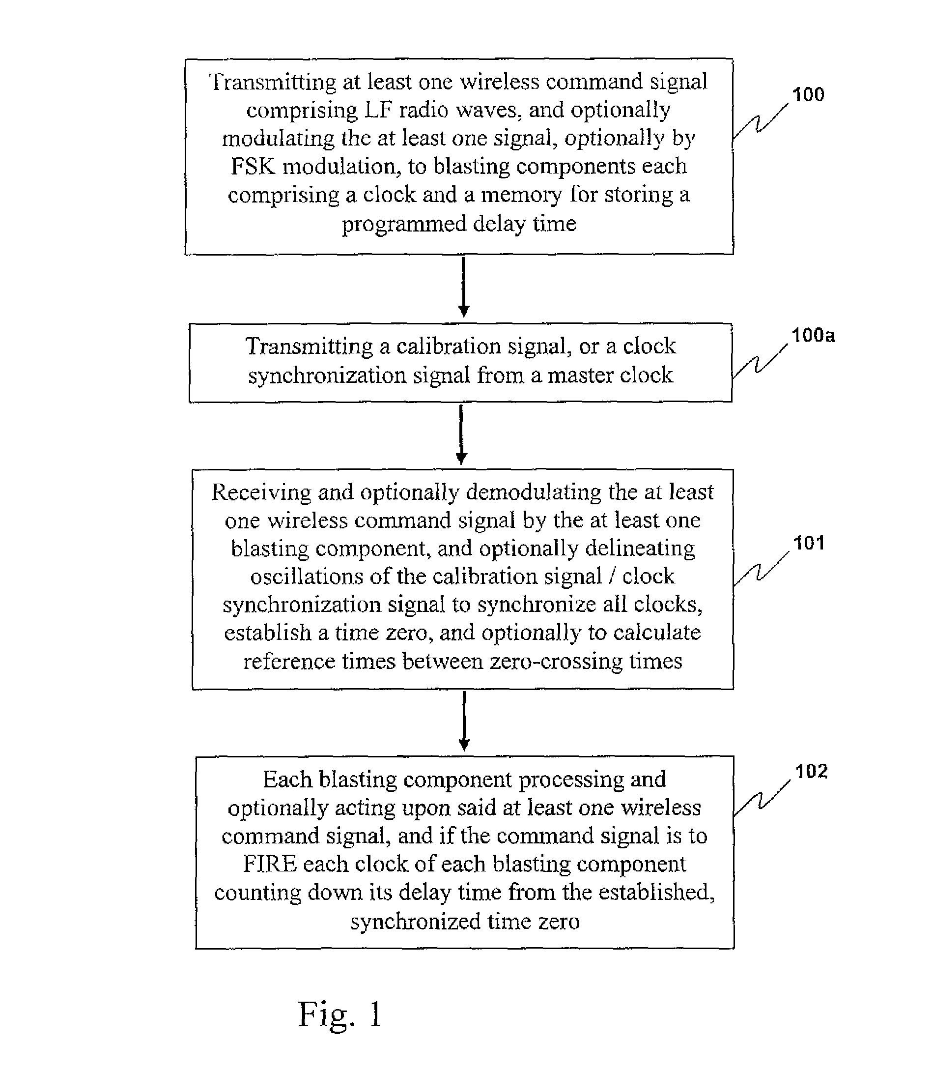
[0109]A preferred method of the invention will be described with reference to FIG. 1. In this method there is provided a method of communicating at least one wireless command signal from at least one blasting machine to at least one blasting component comprising or in operative association with an explosive charge. Step 100 involves the transmitting of at least one wireless command signal from the at least one blasting machine to the at least one blasting component using low frequency radio waves, and optionally modulating the at least one signal, optionally by frequency shift key (FSK) modulation, to blasting components each comprising a clock and a memory for storing a programmed delay time. In step 100a a calibration signal is transmitted, or a clock synchronization signal is transmitted from a master clock. In step 101 there is included the step of receiving the at least one wireless command signal by the at leas...

example 2

Method Involving a Calibration Signal

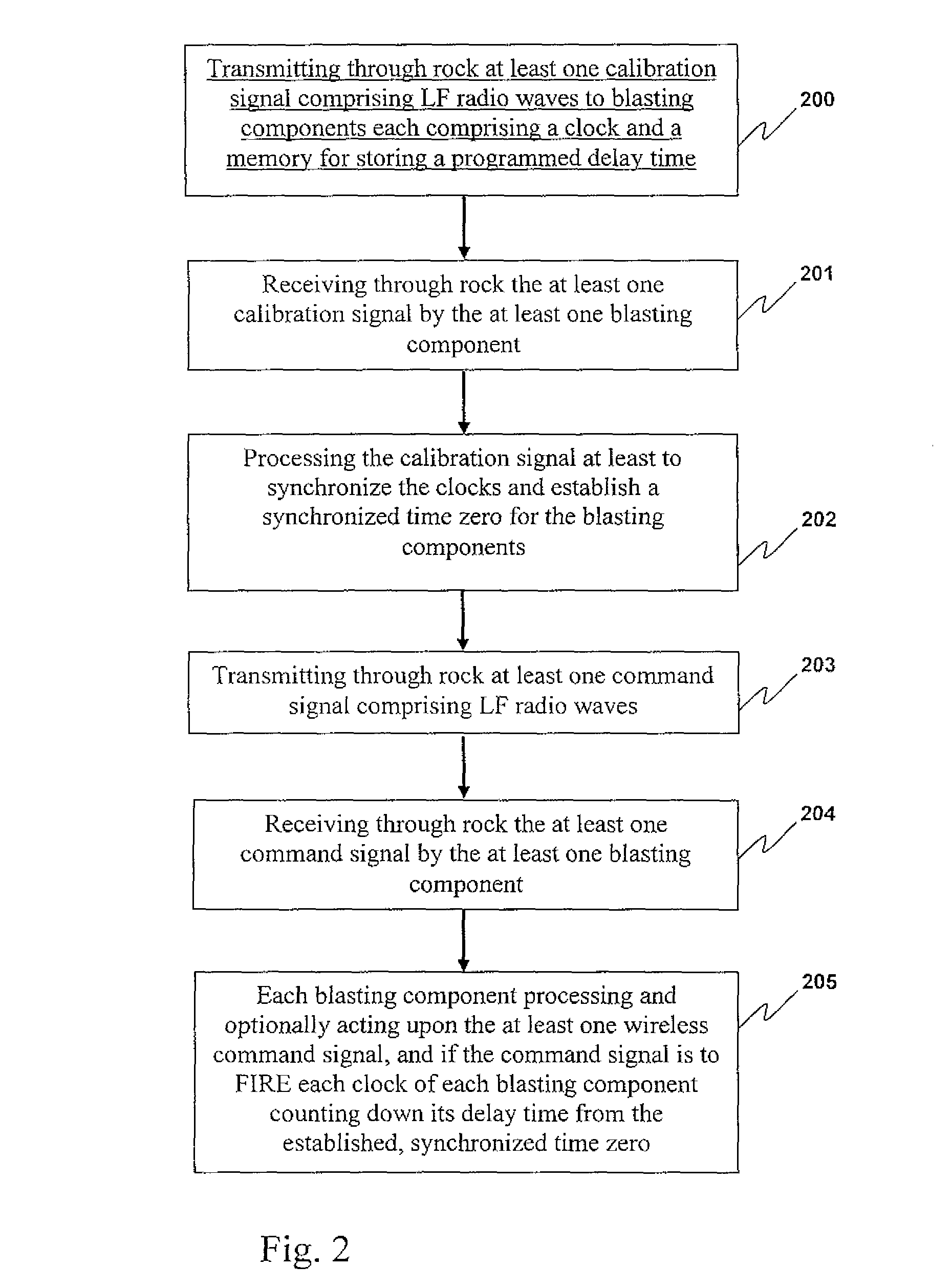
[0110]A preferred method of the invention will be described with reference to FIG. 2. In this method there is provided a method for blasting rock using a blasting apparatus comprising at least one blasting machine on or above a surface of the ground, for transmitting at least one wireless command signal, and at least one blasting component located below a surface of the ground for receiving and acting upon the at least one wireless command signal as required, each blasting component including or in operative association with an explosive charge and comprising a clock and a memory for storing a programmed delay time. Step 200 involves transmitting through rock from each blasting machine or another component of the blasting apparatus a calibration signal having a LF radio wave carrier frequency of from 20-2500 Hz to blasting components each comprising a clock and a memory for storing a programmed delay time. Step 201 involves receiving through rock...

example 3

Binary Coding of a Calibration Signal

[0111]As previously discussed, calibration signals for clock synchronization may be useful if time spacings between, for example, zero-crossings are appropriately calculated. Preferably, the frequency of the signal will remain relatively constant so that the amount of “jitter” in the signal oscillations is reduced, and the blasting component can detect a fairly regular time spacing between zero-crossings. By averaging the time spacings, any jitter in the signal may be compensated for.

[0112]With reference to FIG. 3, there is shown a graph of times between successive zero-crossings received by a blasting component in a test blasting system. It will be noted that for the first 35 zero-crossings detected, a time spacing of an average 48 microseconds is detected. The Figure also shows some experimentation with FSK modulation to generate a binary code for signal transmission as part of the calibration signal. For counts 38 to 43, 48 to 53, 58 to 63, an...


PUM


Abstract

Disclosed herein are methods for communicating wireless signals between components of a blasting apparatus, with the intention of conducting a blasting event. In preferred embodiments, the methods are particularly suited to through -rock transmission of wireless command signals, and optionally wireless calibration or synchronization signals, thereby to achieve timed actuation of explosive charges positioned below ground under the control of one or more blasting machines located at or above a surface of the ground, with a high degree of accuracy. Further disclosed are blasting apparatuses and components thereof suitable for use, for example, in conducting the methods of the invention.

Description

CROSS-REFERENCE TO RELATED APPLICATIONS[0001]This application claims the priority rights of prior U.S. patent applications Ser. Nos. 60 / 795,568 filed on Apr. 28, 2006, and 60 / 813,361 filed on Jun. 14, 2006, both by applicants herein.FIELD OF THE INVENTION[0002]The invention relates to the field of apparatuses and components thereof, for effecting blasting of rock, which employ wireless communication, and methods of blasting employing such apparatuses and components thereof.BACKGROUND TO THE INVENTION[0003]In mining operations, the efficient fragmentation and breaking of rock by means of explosive charges demands considerable skill and expertise. In most mining operations explosive charges, including boosters, are placed at predetermined positions near or within the rock. The explosive charges are then actuated via detonators having predetermined time delays, thereby providing a desired pattern of blasting and rock fragmentation. Traditionally, signals are transmitted to the detonato...

Claims


Application Information

Patent Timeline
Patent Type & Authority Patents(United States)
IPC IPC(8): F23Q7/00
CPCF42C11/06F42D3/04F42D1/055
Inventor STEWART, RONALD F.MCCANN, MICHAEL J.
Owner ORICA EXPLOSIVES TECH PTY LTD
Learn More