
High efficiency turbine and method of generating power

a high-efficiency, unidirectional technology, applied in the direction of wind motor control, non-positive displacement fluid engine components, liquid fuel engine components, etc., can solve the problems of gearing, gearing presents yet another potential mechanical failure mode, and the darrieus turbine fails to self-start, etc., to achieve high power output at low speeds, high efficiency, and easy production

Active Publication Date: 2013-03-12
OCEAN RENEWABLE POWER COMPANY
View PDF38 Cites 10 Cited by
  • Summary
  • Abstract
  • Description
  • Claims
  • Application Information

AI Technical Summary

Benefits of technology

The present invention is a new type of hydropower turbine that solves problems with existing turbines. It is highly efficient, easy to produce, and can be made smaller or larger to meet different power needs. It can work well with different types of water flow and can produce high power at low speeds. This new turbine is a great solution for harnessing energy from a wide range of sites and water flow conditions.

Problems solved by technology

First, the Darrieus turbine fails to self start and requires some initial force to begin rotating in a current.
The Darrieus turbine airfoils thus present a varying angle of attack in relation to current, and this leads to a sinusoidal fluctuation in resultant torque that creates a potentially destructive resonance at a natural frequency of the hydrofoil blades.
Lastly, the shaft of the Darrieus turbine couples with a generator requiring gearing multiplication and that gearing presents yet another potential mode of mechanical failure.
Second, the GHT requires minimal gearing multiplication between the turbine and power generator.
Despite these improvements, the GHT, however, presents some constraints.

Method used


Image

  • High efficiency turbine and method of generating power
  • High efficiency turbine and method of generating power
  • High efficiency turbine and method of generating power

Examples


Embodiment Construction

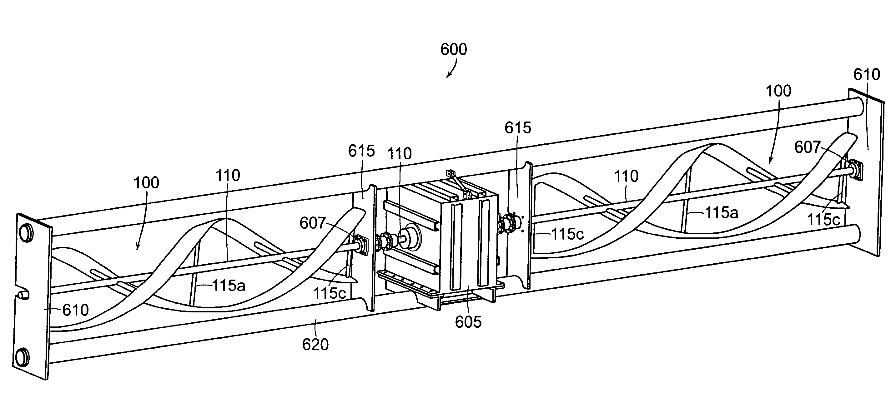
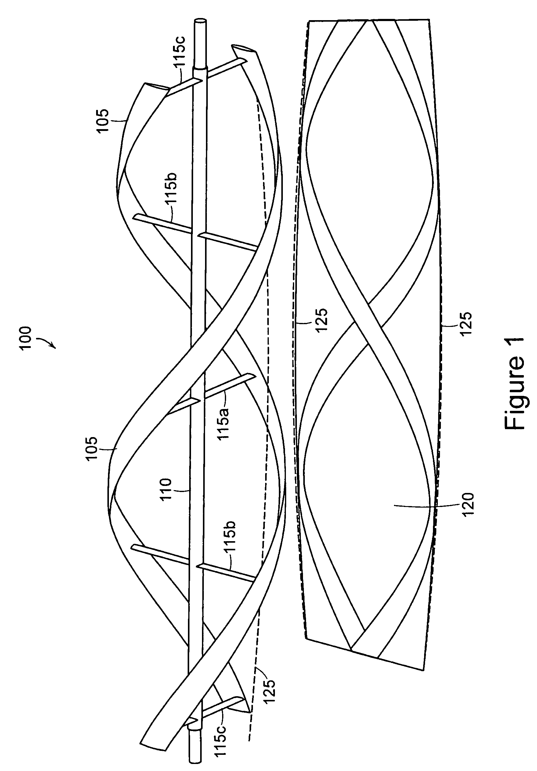
[0041]The present invention includes a turbine and method of making the same. The unique design of the present invention provides for a highly efficient, easily produced, scalable turbine that produces high power output at low fluid velocity and efficiently harnesses energy from a wide range of sites and water flow conditions. The method of making the turbine is a low cost, easily reproduced and scalable process. Various features and advantages of the present invention are described below with reference to several preferred embodiments and variations thereof. Those skilled in the art, however, will understand that alternative embodiments of the structures and methods illustrated herein may be employed without departing from the scope and principles of the described invention.

[0042]As shown in FIG. 1, an exemplary embodiment of the highly efficient turbine 100 of the present invention comprises a plurality of blades 105 tracing a spiral wound path about a central shaft 110. Here, the...


PUM


Abstract

A turbine includes a plurality of blades that rotate in a single direction when exposed to fluid flow, wherein the plurality of blades are joined to the central shaft by a plurality of radial spokes disposed substantially perpendicular to the central shaft such that the rotating plurality of blades causes the shaft to rotate. The plurality of blades has a uniform airfoil-shaped cross section, where the airfoil cross section presents a non-zero angle of attack to the current. The plurality of blades wind in a spiral trajectory, rotating around the central shaft and having a variable radius along the length of the central shaft such that a distance measured from the plurality of blades to the center shaft is greater near the center of the turbine than at either end.

Description

BACKGROUND[0001]1. Field of the Invention[0002]The present invention relates generally to turbines and more specifically to a highly efficient unidirectional turbine that harnesses energy from a fluid flow to produce power.[0003]2. Discussion of Background information[0004]For many years turbines have been harnessing energy from fluid flow to produce power. Windmills, gyromills, delta turbines and cyclomills have long harnessed energy from wind and converted the same to power. Hydropower turbines harness ocean and tidal currents which are capable of providing a virtually inexhaustible supply of emission-free renewable energy. For example, the Darrieus turbine, a wind turbine, and the Gorlov Helical Turbine (GHT), a water turbine, each take a unique approach to harnessing energy in fluid flow to generate power.[0005]The Darrieus wind turbine, a Vertical Axis Wind Turbine (VAWT), comprises vertical airfoils affixed in a symmetric arrangement to a vertical shaft. The vertical shaft con...

Claims


Application Information

Patent Timeline
Patent Type & Authority Patents(United States)
IPC IPC(8): F03B3/12
CPCF03B13/264F03B17/063Y02E10/38F05B2250/25Y02E10/28F05B2240/214Y02E10/30Y02E10/74Y02E10/20
Inventor SAUER, CHRISTOPHER R.MCGINNIS, PATRICKYATSKAR, IGORFIREBAUGH, MILLARD S.
Owner OCEAN RENEWABLE POWER COMPANY
Learn More