
Vehicle behavior control device

a technology of vehicle behavior and control device, which is applied in the direction of driver input parameters, non-deflectable wheel steering, brake components, etc., can solve the problems of deteriorating directional stability of the vehicle, sense of discomfort, etc., and achieve satisfactory directional stability and responsiveness, significant restraint of the sense of discomfort felt by the driver, and the effect of reducing the influence of the frequency response characteristics of the motion state amount generated on the vehicl

Active Publication Date: 2013-03-05
TOYOTA JIDOSHA KK
View PDF13 Cites 2 Cited by
  • Summary
  • Abstract
  • Description
  • Claims
  • Application Information

AI Technical Summary

Benefits of technology

[0006]The present invention has been made to solve the above-mentioned problem, and has an object to provide a vehicle behavior control device capable of providing satisfactory directional stability and responsiveness during the turn of the vehicle, taking into account a frequency response characteristic of a motion state amount generated on a vehicle.
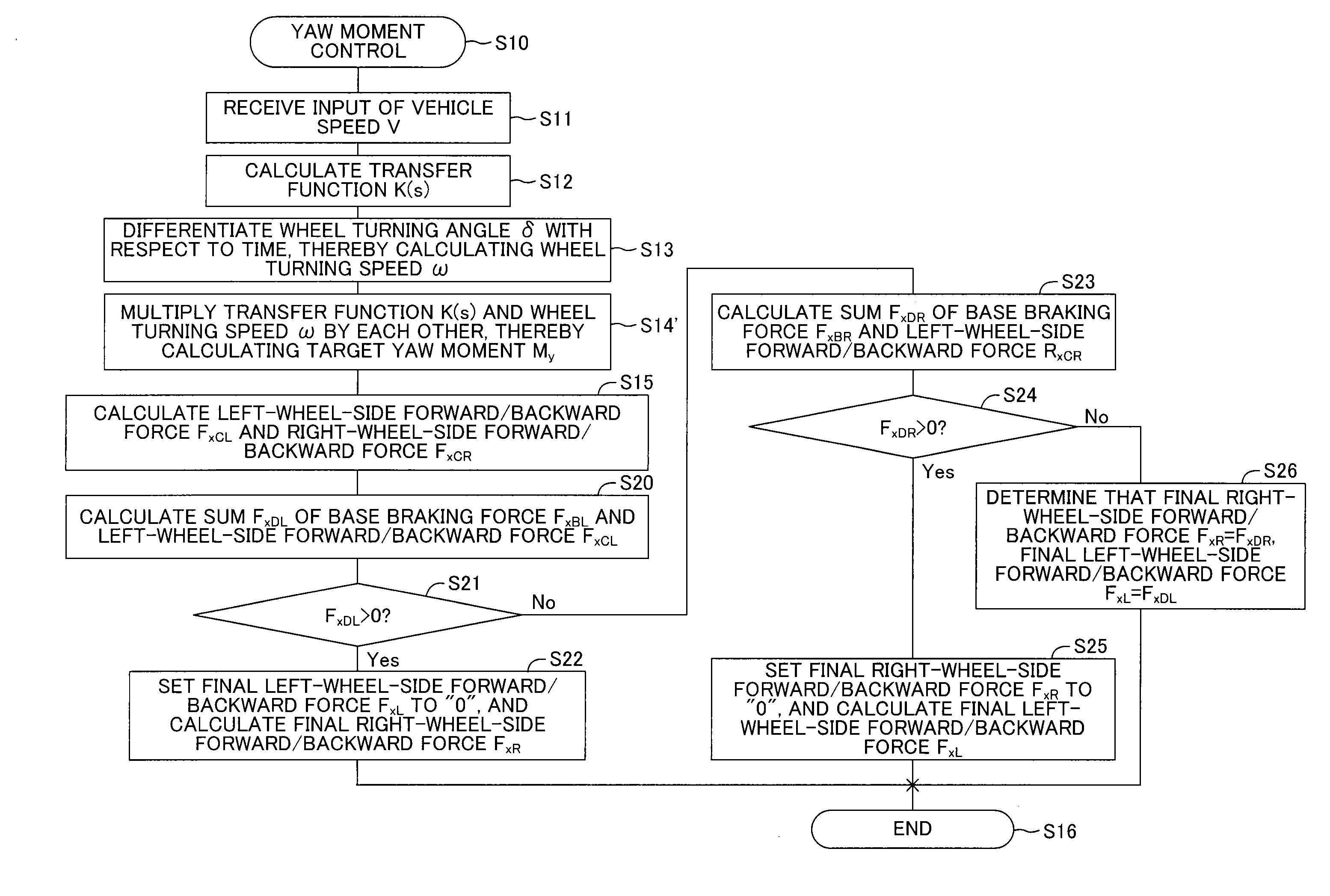
[0019]Moreover, the forward / backward force calculation means can calculate, when the generated direction of the motion state amount generated on the vehicle depending on the operation direction of the steering wheel by the driver and the generated direction of the motion state amount generated on the vehicle by the left-wheel-side forward / backward force and the right-wheel-side forward / backward force are different from each other, namely, the operation direction of the steering wheel by the driver and the generated direction of the target yaw moment (more specifically, the wheel turning direction of the wheel to be turned) are different from each other, the left-wheel-side forward / backward force or the right-wheel-side forward / backward force as “0”. As a result, the sense of discomfort between the motion state amount expected to be generated by the operation of the steering wheel by the driver and the motion state amount (more specifically, the target yaw moment) actually generated on the vehicle can be efficiently restrained.

Problems solved by technology

As a result, the directional stability of the vehicle may be deteriorated, or a driver may feel a sensitive or insensitive responsiveness, and may feel a sense of discomfort.

Method used


Image

  • Vehicle behavior control device
  • Vehicle behavior control device
  • Vehicle behavior control device

Examples


first embodiment

a-1. Modified Example of First Embodiment

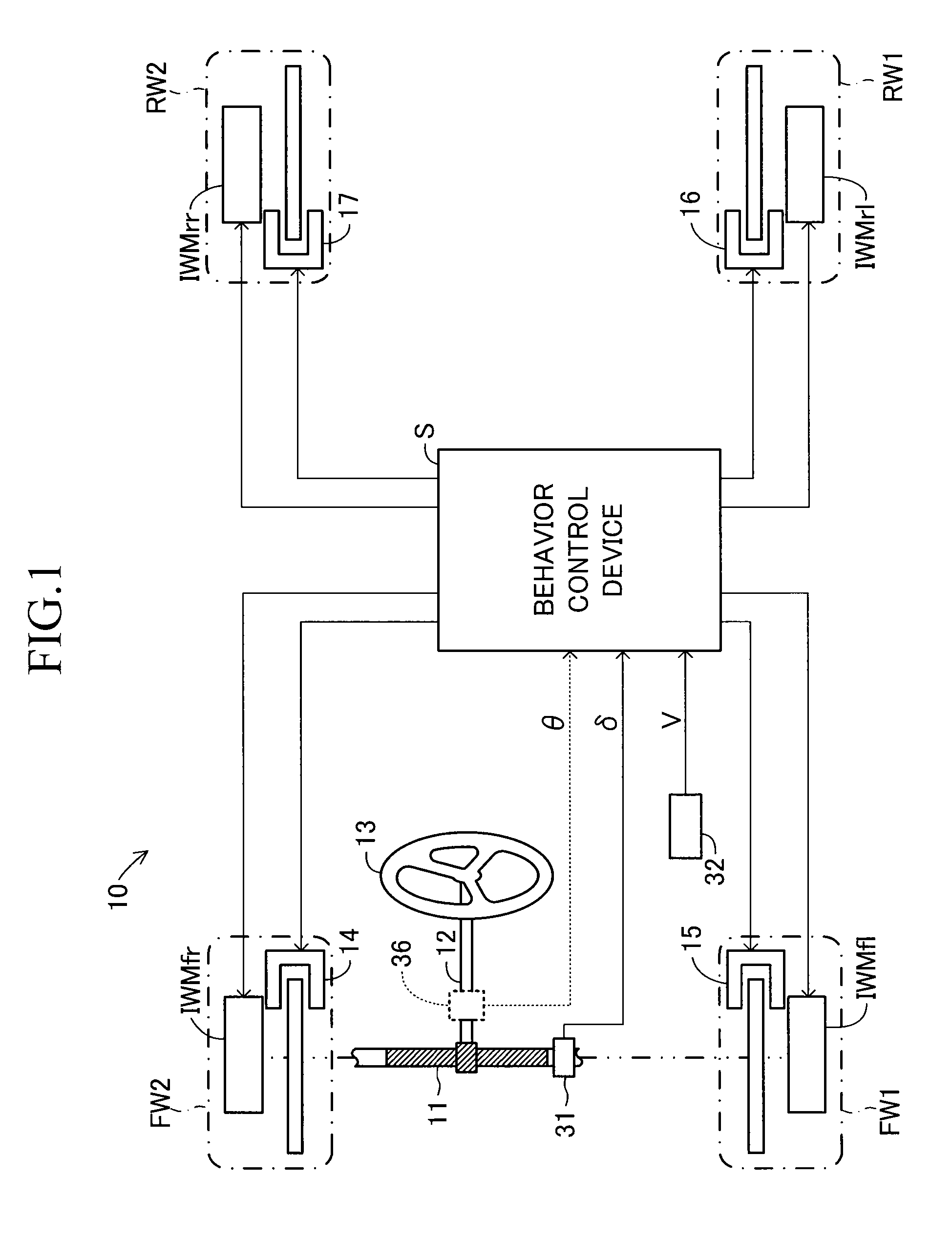
[0097]According to the first embodiment, the left front wheel FW1 and the left rear wheel RW1 as a whole generate the left-wheel-side forward / backward force FxCL, and the right front wheel FW2 and the right rear wheel RW2 as a whole generate the right-wheel-side forward / backward force FxCR, thereby generating the target yaw moment My on the vehicle 10. Specifically, the left front wheel FW1 and the left rear wheel RW1 as a whole generate the braking force (or driving force) coincident with the left-wheel-side forward / backward force FxCL, and the right front wheel FW2 and the right rear wheel RW2 as a whole generate the driving force (or braking force) coincident with the right-wheel-side forward / backward force FxCR, thereby generating the target yaw moment My toward the left direction or the target yaw moment My toward the right direction on the vehicle 10.

[0098]By the way, in general, for a suspension structure on the rear wheel side of a ve...

second embodiment

b. Second Embodiment

[0101]According to the first embodiment and the modified example, in order to generate the target yaw moment My, the braking force (or driving force) coincident with the left-wheel-side forward / backward force FxCL is generated on the left wheel side, and the driving force (or braking force) coincident with the right-wheel-side forward / backward force FxCR is generated on the right wheel side. In other words, according to the first embodiment and the modified example, by using the braking force and the driving force, the target yaw moment My is generated. In this case, by using only the braking force, the target yaw moment My can be generated. A detailed description is now given of a second embodiment, and the same components are denoted by the same reference symbols as those of the first embodiment and detailed descriptions thereof are omitted.

[0102]According to the second embodiment, as indicated by the broken lines of FIG. 1 and FIG. 2, the behavior control devi...


PUM


Abstract

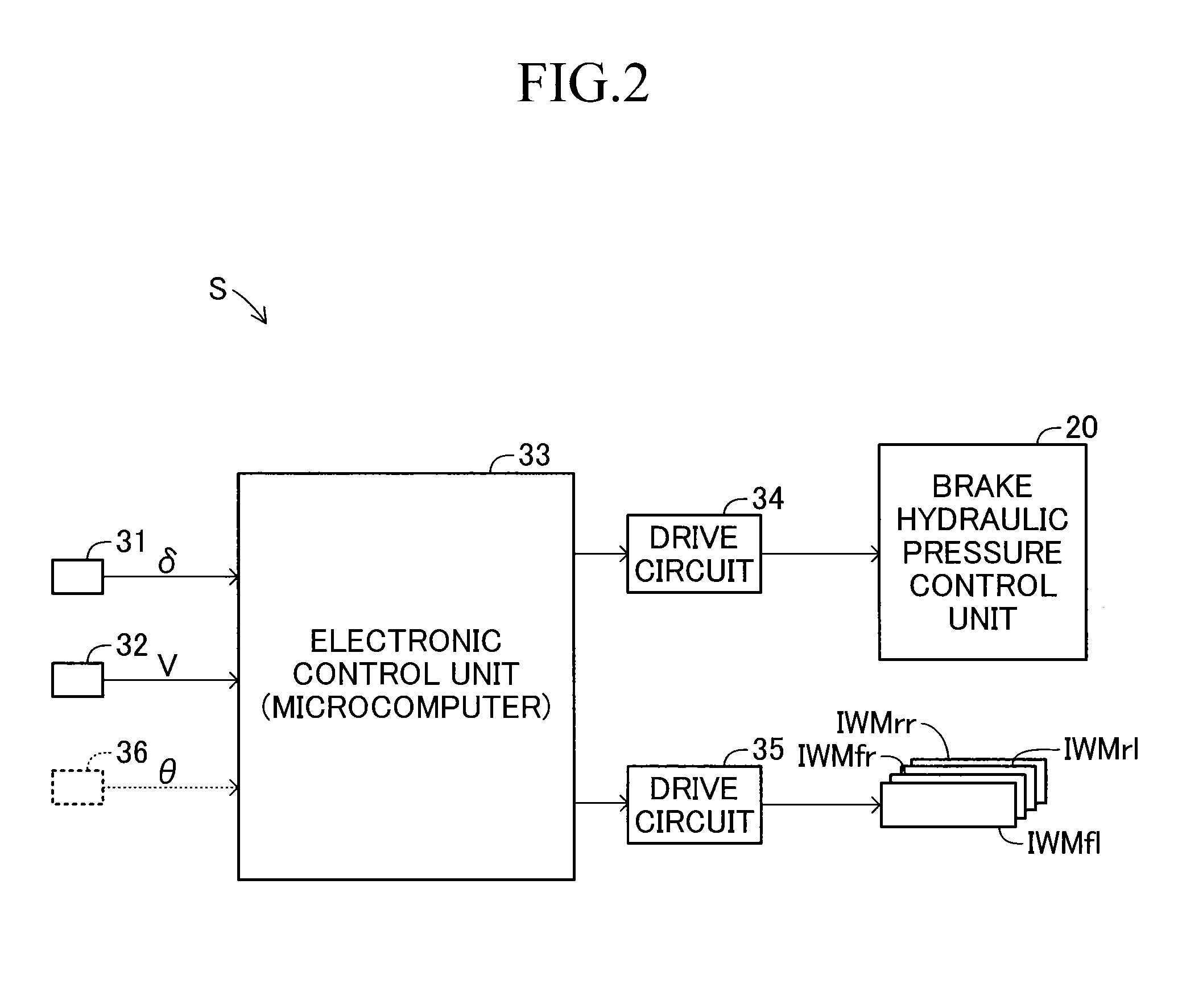
A vehicle behavior control device (S) determines, by using a vehicle velocity (V), a transmission function (K(s)) which is determined based on a specification of the vehicle, receives as an input a wheel turning speed (ω) obtained by differentiating a wheel turning angle (δ) of left and right front wheels (FW1, FW2) with respect to time, and outputs a target yaw moment (My). The device (S) also calculates, by using the determined target yaw moment (My), a left-wheel-side forward / backward force (FxCL) imparted to a left wheel side (left front wheel FW1 and left rear wheel RW1) of a vehicle (10) and a right-wheel-side forward / backward force (FxCR) imparted to a right wheel side (right front wheel FW2 and right rear wheel RW2) of the vehicle (10). Then, the device (S) performs control to drive brake units (14-17) and in-wheel motors (IWMfl, IWMfr, IWMrl, IWMrr) depending on a turning direction of the vehicle (10), with the left-wheel-side forward / backward force (FxCL) serving as a braking force (or driving force) and the right-wheel-side forward / backward force (FxCR) serving as a driving force (or braking force). It is thus possible to ensure directional stability and responsiveness when the vehicle turns, taking into account a frequency response characteristic of a motion state amount generated on the vehicle (10).

Description

TECHNICAL FIELD[0001]The present invention relates to a vehicle behavior control device, and more particularly, to a vehicle behavior control device for securing, by taking into account frequency response characteristics of a motion state amount generated on a vehicle, directional stability and responsiveness during a turn of a vehicle.BACKGROUND ART[0002]Conventionally, proposals for improving directional stability and responsiveness during a turn of a vehicle have been made. For example, Japanese Patent Application Laid-Open (kokai) No. S63-279976 describes a vehicle steering device for determining a hydraulic pressure control value, which increases as a front wheel steering angle increases, and decreases as the vehicle speed increases, and applying a brake hydraulic pressure corresponding to the determined hydraulic pressure control value to a brake device on a steering direction side of front wheels of a pair of left and right brake devices applying braking forces to rear wheels...

Claims


Application Information

Patent Timeline
Patent Type & Authority Patents(United States)
IPC IPC(8): A01B69/00B60W10/18B60W30/045
CPCB60T8/1755B60W10/08B60W10/18B60W30/045B60K7/0007B60W2540/18B60W2720/14
Inventor YAMAZAKI, IPPEI
Owner TOYOTA JIDOSHA KK
Learn More