
Film capacitor

a film capacitor and film cell technology, applied in the field of film capacitors, can solve the problems of very vulnerable temperature of the film cell in the film capacitor b>502/b>, and achieve the effect of effectively cooling heat, stable operation and durable lifespan

Inactive Publication Date: 2013-02-26
KIA MOTORS CORP +1
View PDF13 Cites 0 Cited by
  • Summary
  • Abstract
  • Description
  • Claims
  • Application Information

AI Technical Summary

Benefits of technology

The present invention provides a film capacitor that can operate stably and have a long lifespan even when mounted in high-temperature environments such as engine rooms and trunk rooms. This is achieved by effectively cooling the heat generated from the film cell of the film capacitor.

Problems solved by technology

Although a film capacitor 502 has high voltage resistance and durable lifespan, a film cell in the film capacitor 502 is very vulnerable to temperature.

Method used


Image

  • Film capacitor
  • Film capacitor
  • Film capacitor

Examples


Embodiment Construction

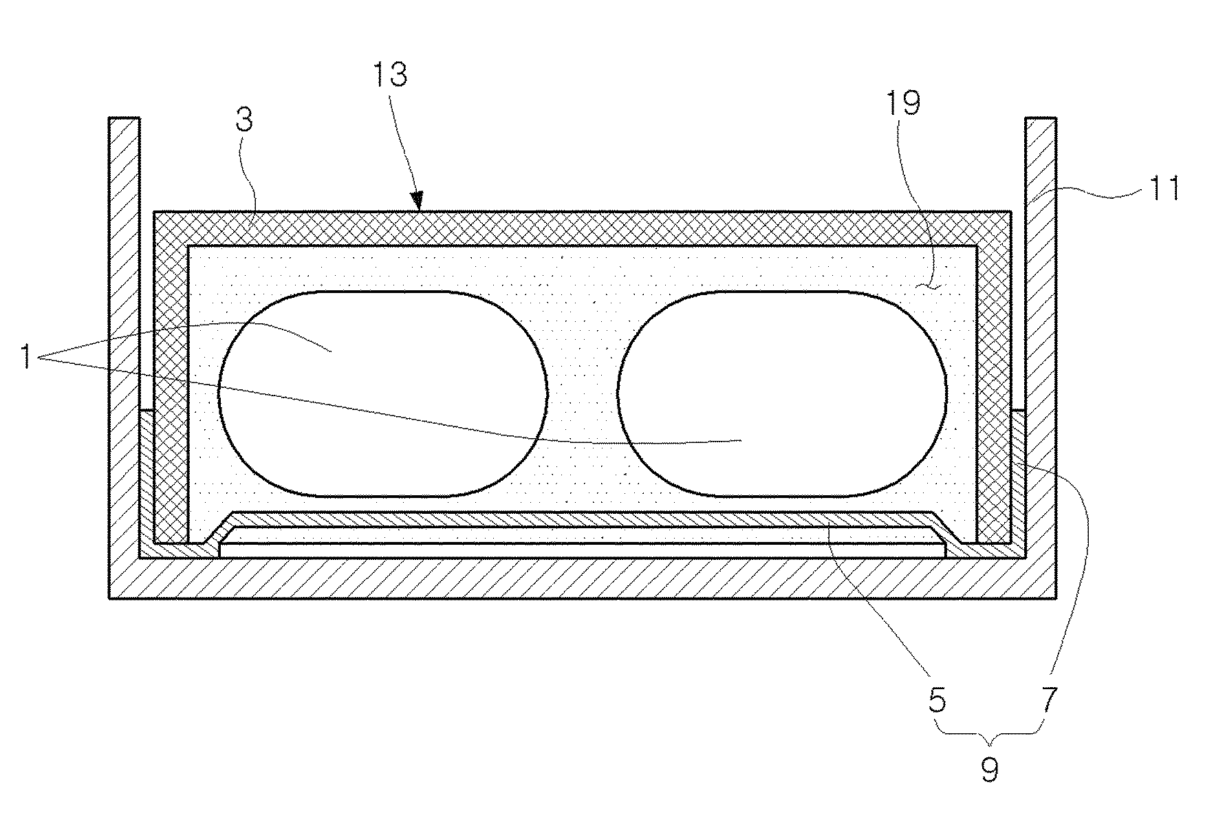
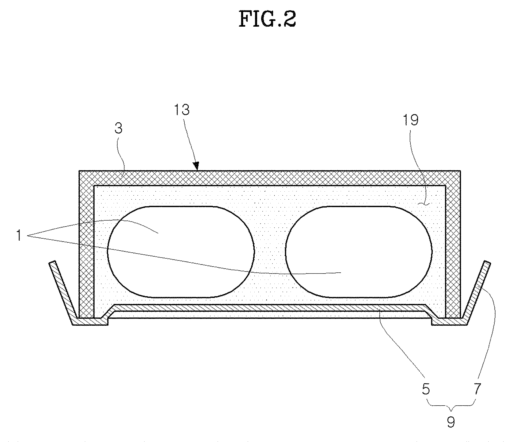
[0026]Referring to FIGS. 2 to 5, a film capacitor includes a case 3 and a heat radiating plate 9. The case 3 includes at least one film cell 1 therein. The heat radiating plate 9 includes a heat absorption unit 5 and a heat radiating unit 7. The heat absorption unit 5 and the heat radiating unit 7 may be formed integrally or in separate units. The heat absorption unit 5 is positioned adjacent to the film cell 1 while not being in contact with the film cell 1. The heat radiating unit 7 is exposed to the outside of the case 3.

[0027]The case 3 may be a container of which one surface is opened. In the heat radiating plate 9, the heat radiating unit 7 is exposed to the outside of the case 3 through the opened surface of the case 3. The film cell 1 and the heat absorption unit 5 may be molded in an epoxy inside the case 3 together with a bus bar 17 that is connected with the film cell 1 to secure an electrical connection state to the outside of the case 3, such that only the heat radiatin...


PUM


Abstract

A film capacitor is provided that includes a case in which a film cell is incorporated and a heat radiating plate including a heat absorption unit being positioned adjacent to the film cell while not being in contact with the film cell for absorbing heat and a heat radiating unit being exposed to the outside of the case. Preferred film capacitors can perform a stable operation and have durable lifespan, even when an inverter adopting the film capacitor is mounted on a trunk room and an engine room, by effectively cooling heat generated from a film cell of the film capacitor.

Description

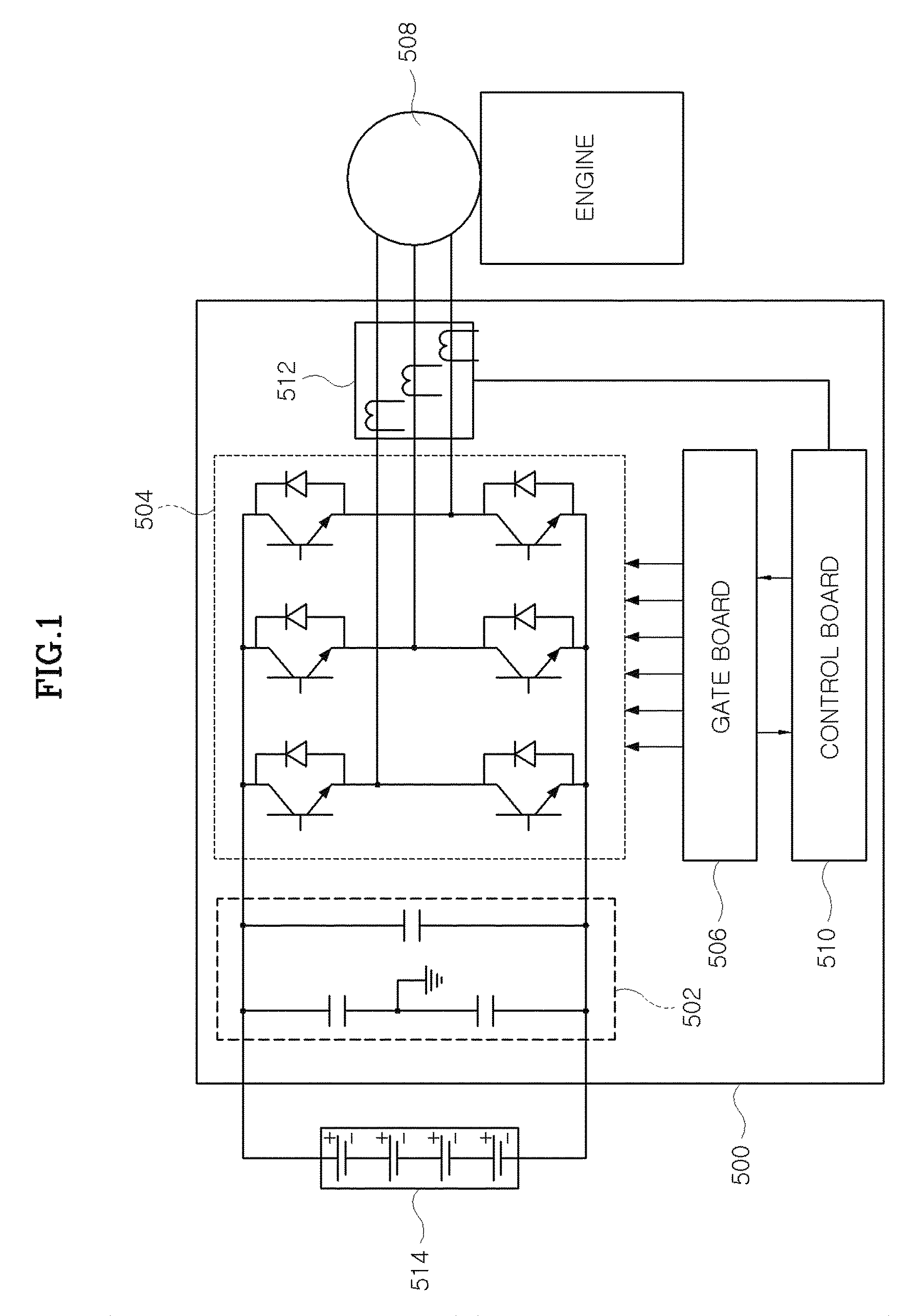
CROSS-REFERENCE TO RELATED APPLICATIONS[0001]The present application claims priority to Korean Patent Application Number 10-2008-0116609 filed Nov. 24, 2008, the entire contents of which application is incorporated herein for all purposes by this reference.TECHNICAL FIELD[0002]The present invention relates to a film capacitor used for an inverter of a hybrid vehicle.BACKGROUND ART[0003]An inverter in a hybrid vehicle supplies electricity required for driving a motor / generator and charges a high-voltage battery with the electricity generated by the motor / generator, between the high-voltage battery and the motor / generator.[0004]Referring to FIG. 1, an inverter 500 includes a capacitor 502, a power module 504 that is constituted by a power conversion switching element, a gate board 506 for driving the power module 504, a control board 510 for controlling torque and speed of a motor / generator 508, and a current measurement device 512 for measuring 3-phase current required for the contro...

Claims


Application Information

Patent Timeline
Patent Type & Authority Patents(United States)
IPC IPC(8): H01G2/08H01G4/005
CPCH01G2/04H01G2/08H01G4/32Y02T10/7022Y02T10/70H01G4/33H01G4/224
Inventor LEE, JEONGYUNHAN, DAEWOONGKANG, GUBAEJEON, WOOYONGYOO, IN-PILYIM, JEONGBINNAM, DONGJINJUNG, JINHWANJOO, JUNGHONG
Owner KIA MOTORS CORP
Learn More