
Piston pump with improved piston

a piston pump and piston technology, applied in the field of piston pumps, can solve the problems of complicated and expensive plunge grinding procedures, and the production cost of known pistons is quite high, and achieve the effects of improving suction performance, reducing flow resistance, and producing especially simple and economically

Active Publication Date: 2013-02-26
ROBERT BOSCH GMBH
View PDF10 Cites 4 Cited by
  • Summary
  • Abstract
  • Description
  • Claims
  • Application Information

AI Technical Summary

Benefits of technology

This design significantly reduces flow resistance and enhances suction performance, leading to improved pressure buildup dynamics and increased pump efficiency, making the piston pump more cost-effective and efficient.

Problems solved by technology

In addition, the known piston pumps have stepped pistons, for which a very complicated and expensive plunge grinding procedure is required.
Thus the known pistons are quite expensive to produce and furthermore have a relatively high flow resistance, because of the deflection of the fluid from the transverse bore into the longitudinal bore.

Method used


Image

  • Piston pump with improved piston
  • Piston pump with improved piston
  • Piston pump with improved piston

Examples


Embodiment Construction

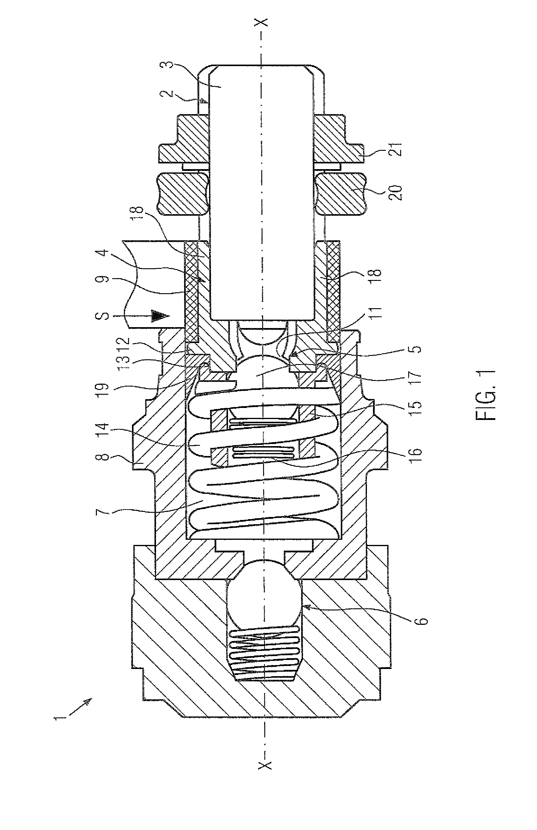
[0019]Below, a piston pump 1 in one exemplary embodiment of the invention will be described, in conjunction with FIGS. 1 and 2.

[0020]As shown in FIG. 1, the piston pump 1 includes a piston 2 and a cylinder 8. The piston 2 can be driven in a known manner by means of an eccentric element. Upon the piston being driven, fluid is aspirated from the direction of the arrow S radially through a filter 9. The fluid is then delivered into a pressure chamber 7 in the axial direction X-X of the piston. The pressure chamber 7 is disposed in the cylinder 8 between an inlet valve 5 and an outlet valve 6. A restoring spring 14 for the piston is also disposed in the pressure chamber 7.

[0021]The inlet valve 5 is embodied as a check valve and includes a cage 15, in which a spring 16 and a ball 17 are disposed. The outlet valve 6 is likewise embodied as a spring-loaded check valve, and it opens as soon as a pressure in the pressure chamber 7 is greater than a spring force acting on the ball of the outl...


PUM


Abstract

The invention relates to a piston pump for conveying a fluid, in particular in a vehicle brake system. The piston pump has a cylinder and a piston movably disposed in the cylinder. A restoring element preloads the piston, and a drive unit for actuates the piston in the cylinder to pump the fluid into a pressure chamber formed in the cylinder. The piston is embodied by a first piston par and a second piston part. The first piston part is a cylindrical body, which can be moved by the drive unit. The second piston part form the piston base, in which four radial inlet openings and one axial connection opening for communication with the pressure chamber are disposed. A flange for the disposition of a seal is disposed on the outer circumference of the piston base element. The openings are simple to make in the face ends and circumferential regions of the second piston part.

Description

CROSS-REFERENCE TO RELATED APPLICATION[0001]This application is a 35 USC 371 application of PCT / EP 2006 / 065686 filed on Aug. 25, 2006.BACKGROUND OF THE INVENTION[0002]1. Field of the Invention[0003]The invention relates to a piston pump for pumping a fluid, having an improved piston, which pump is used in particular in brake systems of vehicles.[0004]2. Description of the Prior Art[0005]Piston pumps are known from the prior art in various versions. Know piston pumps are used for instance in vehicle brake systems that make an active pressure buildup as a function of predetermined driving situations possible. Examples of such brake systems are ABS, ESP or traction control systems. The response performance and pressure buildup of such piston pumps must be quite good, so that a control intervention in the brake system can be made as fast as possible.[0006]In the known piston pumps, pistons are used that implement a delivery of the fluid by the piston. On the one hand, at least one trans...

Claims


Application Information

Patent Timeline
Patent Type & Authority Patents(United States)
IPC IPC(8): F04B19/00F16J1/00
CPCB60T8/4031F04B1/0408F04B53/14
Inventor SCHULLER, WOLFGANGZIMMERMANN, MARC
Owner ROBERT BOSCH GMBH
Learn More