Switched optical fibre network for airplane seats

a technology of optical fiber network and seat, which is applied in the direction of fiber transmission, bidirectional transmission, transmission, etc., can solve the problems of heavy network type, difficult connection to connector, and risk of corrosion,

Active Publication Date: 2013-02-19
SIT
View PDF6 Cites 3 Cited by
  • Summary
  • Abstract
  • Description
  • Claims
  • Application Information

AI Technical Summary

Benefits of technology

The present invention proposes to overcome the drawbacks of optical networks by replacing simple couplers with active optical switches of the MEMS type. These switches can orient the light signal in two directions, one stable and one temporary. The temporary position is achieved when voltage is applied to the switch. The switch is a positive safety device that returns to an inactive position in case of failure of the control electronics or power supply. The optical network is suitable for high-capacity airplanes and includes screens connected to each other via an optical fiber, an upstream and downstream switching box, and a transceiver for converting the light signal into an electric signal. The network also includes a server for sending data to the screens. The technical effect of the invention is to improve the reliability and safety of optical networks for airplane seats.

Problems solved by technology

This type of network has the drawback of being heavy since copper is a high-density metal.
However, since aluminum is not used very widely—at least for cables of small sections, it poses difficulties in terms of connecting to connectors, as well as in terms of contact quality and risk of corrosion.
In addition, this type of network produces a relatively intense electromagnetic field, which makes it necessary to take a lot of precautions as much for preventing interference with electronic equipment in the vicinity as for being parasitized by the equipment of the airplane.
Moreover, as the network switches 4.1-4.3 do need a power supply, the risks of failure can never be entirely eliminated.
Not only are passengers deprived of their entertainment programs, but, more importantly, the safety instructions can no longer be displayed on a significant number of seats.
In fact, a passive optical network can hardly serve more than 12 seats, which makes it necessary either to multiply the number of optical fibers or to re-amplify the light signal every 12 couplers, in which case, we again find the risks of failures of the Ethernet bus affecting copper cables.

Method used


Image

  • Switched optical fibre network for airplane seats
  • Switched optical fibre network for airplane seats
  • Switched optical fibre network for airplane seats

Examples


Embodiment Construction

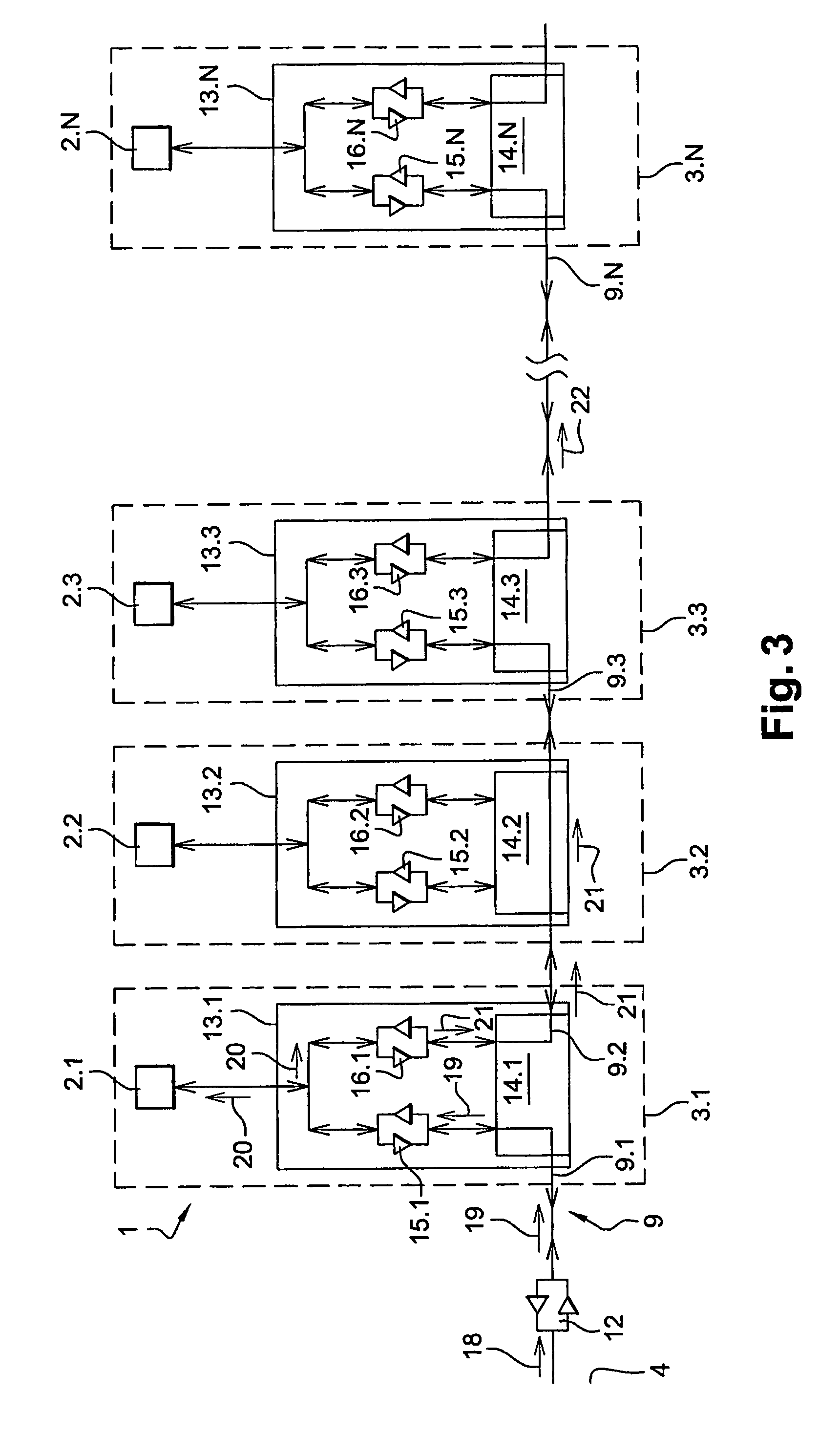
[0039]Identical components retain the same reference from one figure to the next.

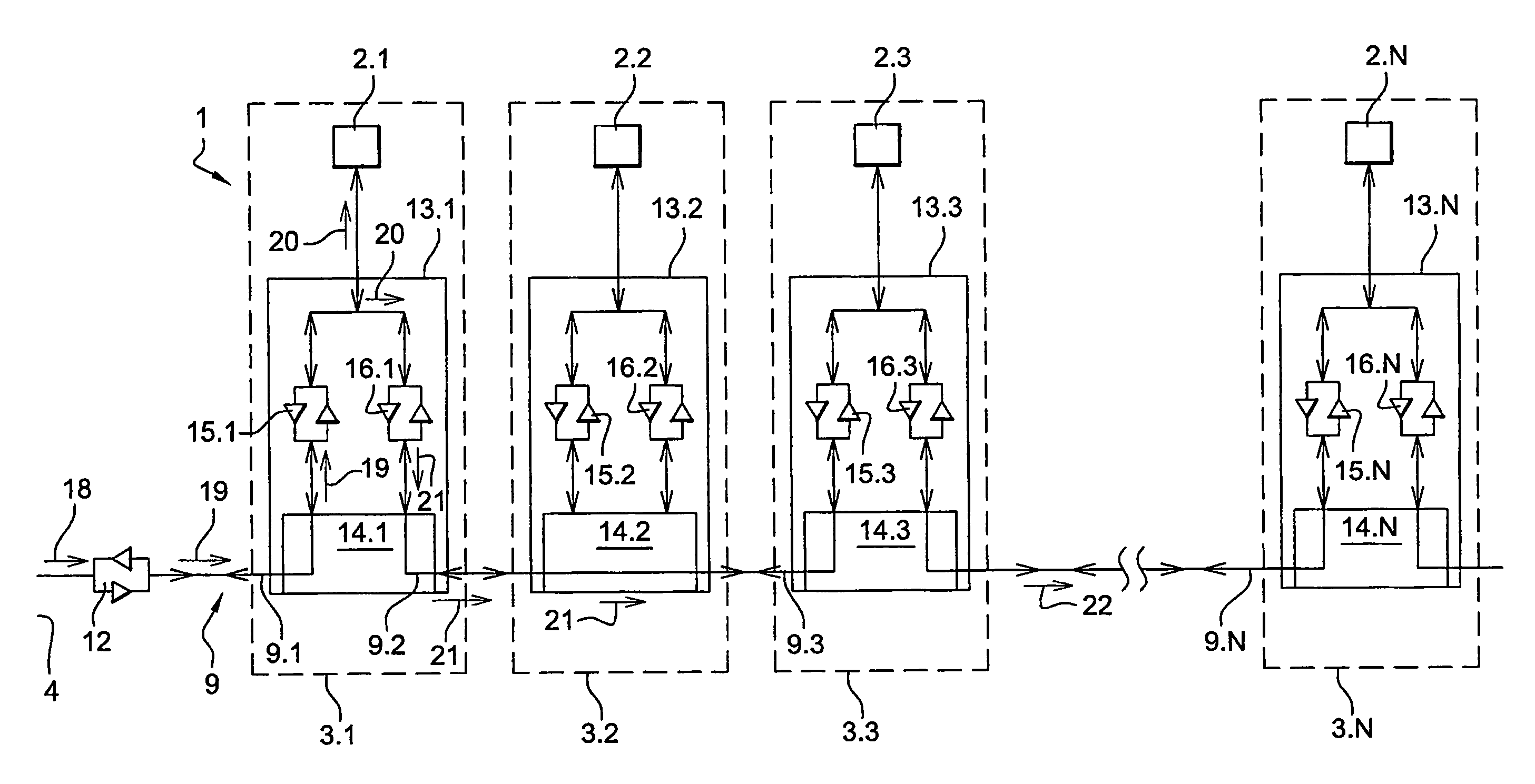
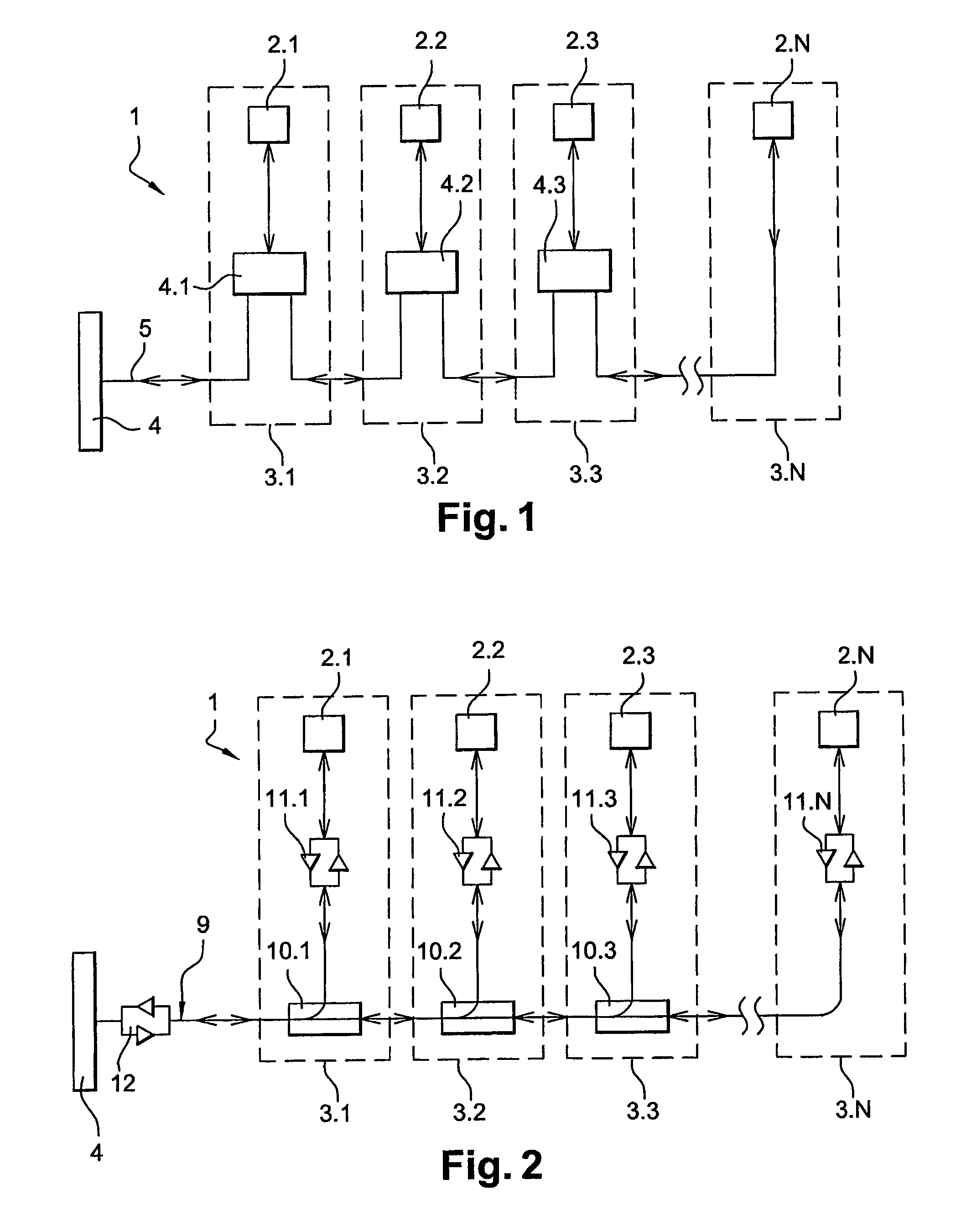
[0040]FIG. 3 shows a switched optical fiber network 1 for airplane seats 3.1-3.N. This network 1 comprises screens 2.1-2.N connected to each other and to a server 4 via an optical fiber 9. These screens 2.1-2.N each comprise a computer (not shown) provided with a network card which enables them to exchange data on an Ethernet type network.

[0041]These screens 2.1-2.N are connected to the optical fiber 9 via switching boxes 13.1-13.N connected in series to each other. Each switching box 13.1-13.N comprises an optical switch 14.1-14.N and two transceivers 15.1-15.N and 16.1-16.N (transceivers in English) connected, on the one hand, to the optical switch 14.1-14.N and, on the other hand, to the screen 2.1-2.N. The server 4 is also provided with a transceiver 12 connected, on the one hand, to this server 4 and, on the other hand, to the optical fiber.

[0042]The transceivers 12 and 15.1-15.N convert the electr...


PUM


Abstract

The invention relates to a network of switched optical fiber for airplane seats. The network connects the screens of the seats to each other and to a server via an optical fiber. The network includes optical switches of the MEMS type including mirrors, said switches being provided perpendicular to each seat. Each switch delivers the light beam in the optical fiber to the screen with which it is connected and re-amplifies it in the optical fiber when it is powered, while the switch directly delivers the light beam to the following seat when it is not powered.

Description

[0001]This application claims priority of PCT International Application No. PCT / FR2008 / 050018 filed on Jan. 7, 2008. The contents of which are incorporated herein by reference.FIELD OF THE INVENTION[0002]The present invention pertains to a switched optical fiber network for airplane seats. The object of the present invention is especially to secure such a network in case of failure of one of its switching elements.BACKGROUND[0003]Generally, in an airplane, screens are integrated in each seat as much for the broadcasting of entertainment programs (music, films, video games, etc.) as for the transmission of safety messages (buckling of belts, use of electronic devices, etc.). These screens are connected within a network to a central computer or server.[0004]Thus, FIG. 1 shows a prior-art network 1, in which screens 2.1-2.N of seats 3.1-3.N are connected to a server 4. These screens 2.1-2.N are connected to the server 4 via network switches 4.1-4.3 or switches. These switches 4.1-4.3 t...

Claims


Application Information

Patent Timeline
Patent Type & Authority Patents(United States)
IPC IPC(8): H04J14/02H04B10/25
CPCH04B10/2503H04B10/2589
Inventor BOUET, LOICGUICHARD, BENOITMARQUET, JEROME
Owner SIT
Why Eureka
Try Eureka