
Computer-aided image interpretation method and device

a computer-aided image and interpretation technology, applied in the field of remote sensing image analysis, can solve the problems of increasing the number of artificial interpretations, the difficulty of providing the wrong kind of feature, and the difficulty so as to achieve the effect of reducing the ambiguity of visual interpretation by humans for the same feature and easy obtaining high accuracy

Active Publication Date: 2013-02-19
HITACHI LTD
View PDF7 Cites 0 Cited by
  • Summary
  • Abstract
  • Description
  • Claims
  • Application Information

AI Technical Summary

Benefits of technology

This method reduces ambiguity in human interpretation, increases accuracy, and reduces the time required for obtaining highly accurate interpretation results by efficiently identifying and modifying incorrect features, thereby decreasing the overall workload.

Problems solved by technology

However, there is a possibility of providing a wrong kind of feature because humans perform the interpretation work of the feature.
Thus, it takes a very long time to visually interpret such an image to every corner, which is a problem.
The image from several satellites might be used for interpretation of more accurate features, but there was a problem in that the amount of interpretation work increased as much as the number of artificial satellites.
But, if the image appropriate for the interpretation of the feature is expanded and displayed, it takes time to display a vast image on the display with limited size or to scroll the image, and working hours are increased.
In addition, there has been a possibility of missing the feature out.
However, the automatic classification technology is not perfect, and the appearance of the feature in the remote sensing image might change greatly and the classification result might also change greatly, with variability characteristics of the sensor of the platform, the weather at the time of taking a picture, and the lighting condition of the location of taking a picture, etc.
Therefore, there has been a problem in that the interpretation result is not consistent when the automatic classification result is substituted as the interpretation result.

Method used


Image

  • Computer-aided image interpretation method and device
  • Computer-aided image interpretation method and device
  • Computer-aided image interpretation method and device

Examples


first embodiment

[0038]In the first embodiment, it is described for the remote sensing image where the radiated and the reflected electromagnetic wave of the ground level is measured and recorded with sensors of platforms such as aircrafts, helicopters, balloons, and artificial satellites, etc. Moreover, the adaptive target of the present application is not limited to the remote sensing image taken a picture with sensors mounted on platforms. Thus, the present application is applicable to the sensing image, if the sensing image is the image taken picture of in various situations such as that the position and the date and time of observation of the observation sensor is previously known, and there is a certain distance between an observation target and a observation sensor.

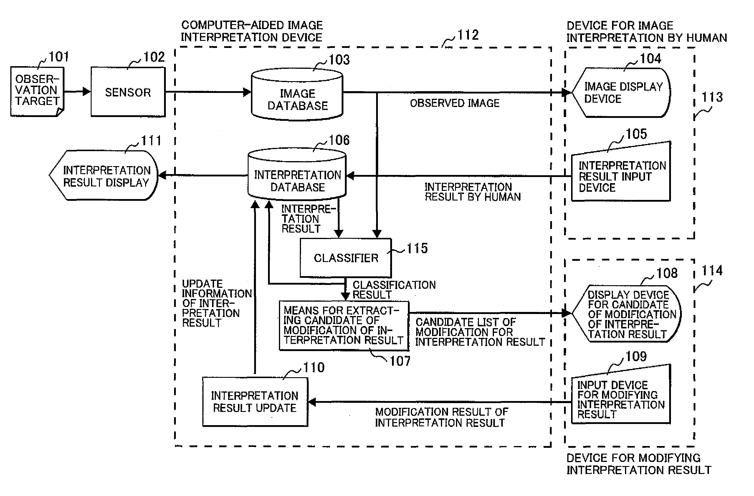
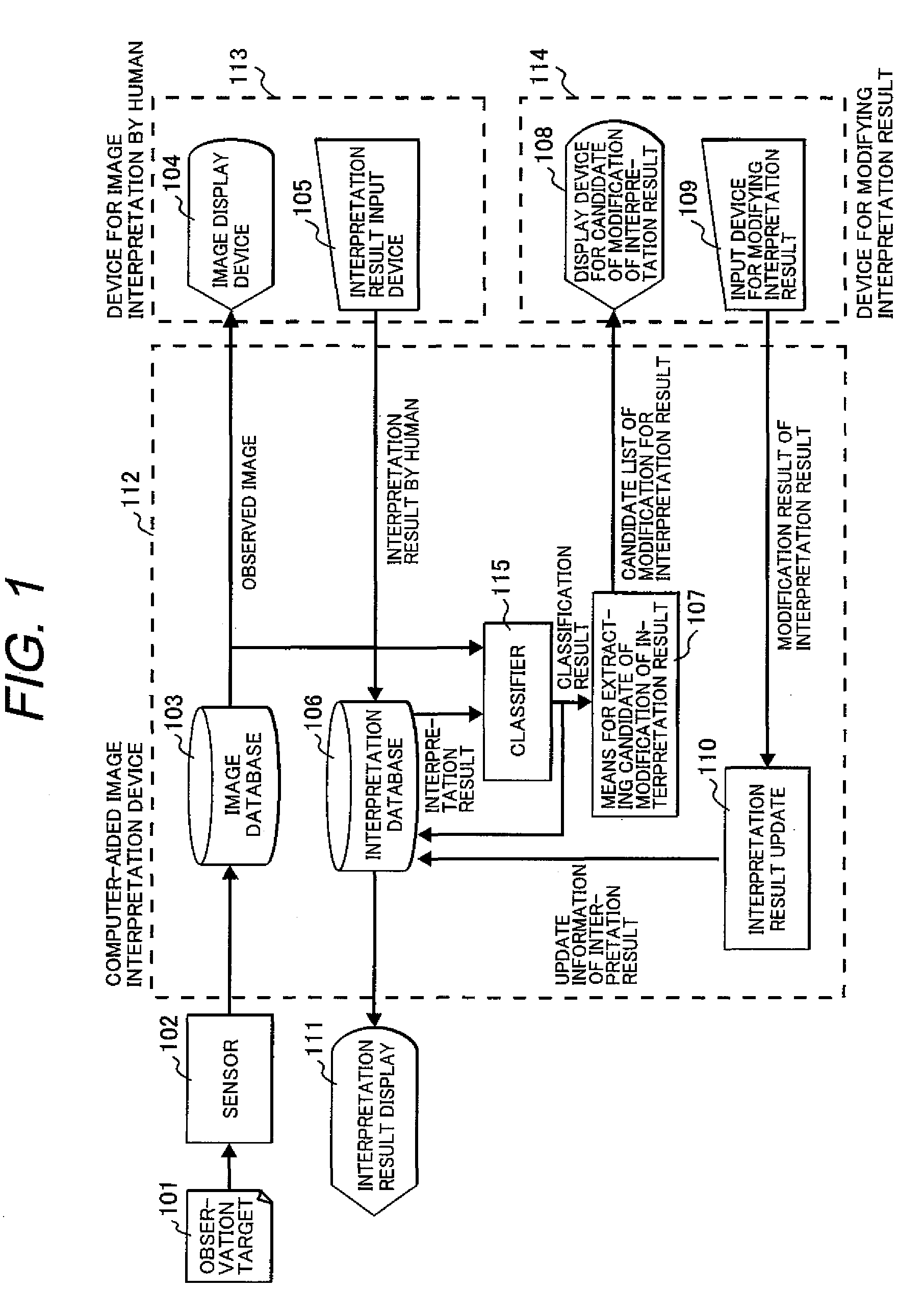
[0039]FIG. 1 is a block diagram that depicts the first embodiment of the computer-aided image interpretation device. The computer-aided image interpretation device 112 obtains an observation signal from an observation sensor 102, a...

second embodiment

[0064]Next, the second embodiment is described. In the following, it will be described for the difference with the first embodiment. In the second embodiment, the automatic classification is executed before the visual interpretation, unlike the first embodiment.

[0065]FIG. 16 is a drawing that depicts the image interpretation supporting flow in the second embodiment. The image interpretation supporting flow is outlined referring to FIG. 16, as follows. First of all, the observation target 101 is taken of a picture with the observation sensor 102. The result of taking a picture is stored in the image database 103 (S1601). The feature that is taken of the picture in the image is automatically classified and the similarity is provided to each feature (S1602). The image is displayed in the image display device 104, and the visual interpretation work is performed by humans with the image display device and the interpretation result input device shown in FIG. 4 (S1603). After that, the fea...

third embodiment

[0072]Next, the third embodiment is described below. In the following, the difference with the first embodiment will be described. FIG. 7 shows one exemplary flow of the means for extracting candidate of modification of interpretation result 107 of the computer-aided image interpretation device related to the third embodiment.

[0073]Here, assuming that the interpretation result data of N piece is included in the interpretation result database 106, the following process is performed for the ith image (1≦i≦N) (S701). When the name of feature is j, all features that the user interpreted are searched, while examining all features included in the interpretation result data of ith image (S702). The amount of characteristic is extracted from the image for each feature k (1≦k≦M) (S703). Here, M is the number of features included in the ith interpretation result data.

[0074]Next, the likelihood L that the name of feature k seems to be the name j of feature is calculated, referring to the inter...


PUM


Abstract

A computer-aided image interpretation method and a device thereof to easily obtain an accurate image interpretation result are provided. An automatic classification means of the image interpretation device performs automatic classification by one of spectral characteristics, radiometric characteristics, diffuse characteristics, textures and shapes, or combinations thereof and accumulates data to an interpretation result database, for plural features of the same kind obtained by interpreting a remote sensing image obtained with an observation sensor. A means for extracting candidate of modification of interpretation result extracts the candidate of modification of interpretation result by comparing likelihoods that are the automatic classification results. A reinterpretation is performed for the candidate of modification of interpretation, and an interpretation result database is updated by an interpretation result update means. As a result, modification of the interpretation work can be efficiently performed.

Description

CLAIM OF PRIORITY[0001]The present application claims priority from Japanese patent application JP2008-097127 filed on Apr. 3, 2008, the content of which is hereby incorporated by reference into this application.BACKGROUND OF THE INVENTION[0002]1. Field of the Invention[0003]The present invention relates to an image analysis using a remote sensing image, and in particular, a computer-aided image interpretation technology.[0004]2. Description of the Related Art[0005]Various features exist in images (hereinafter described as the remote sensing image) shot by platforms such as aircrafts, helicopters, balloons, artificial satellites, and etc. It is described as a visual interpretation, an image interpretation or simply an interpretation, to distinguish these features by manpower.[0006]It is possible to obtain various information by visual interpretation of the remote sensing image. For example, the remote sensing image obtained from the sky in the region struck by an earthquake, a fire,...

Claims


Application Information

Patent Timeline
Patent Type & Authority Patents(United States)
IPC IPC(8): G06K9/62G06K9/66G06K9/64G06V20/13
CPCG06K9/0063G06V20/13
Inventor MINE, RYUJIKAZAMA, YORIKOISHIMARU, NOBUHIRO
Owner HITACHI LTD
Learn More