
Optical impact control system

a control system and optical technology, applied in the direction of orthogonal multiplex, lighting and heating apparatus, instruments, etc., can solve the problems of limited performance range of non-lethal weapon systems, insufficient short distances for proper protection of law enforcement, and the effect of preventing the effect of countermeasures

Active Publication Date: 2013-02-19
MERCURY MISSION SYST LLC
View PDF58 Cites 9 Cited by
  • Summary
  • Abstract
  • Description
  • Claims
  • Application Information

AI Technical Summary

Benefits of technology

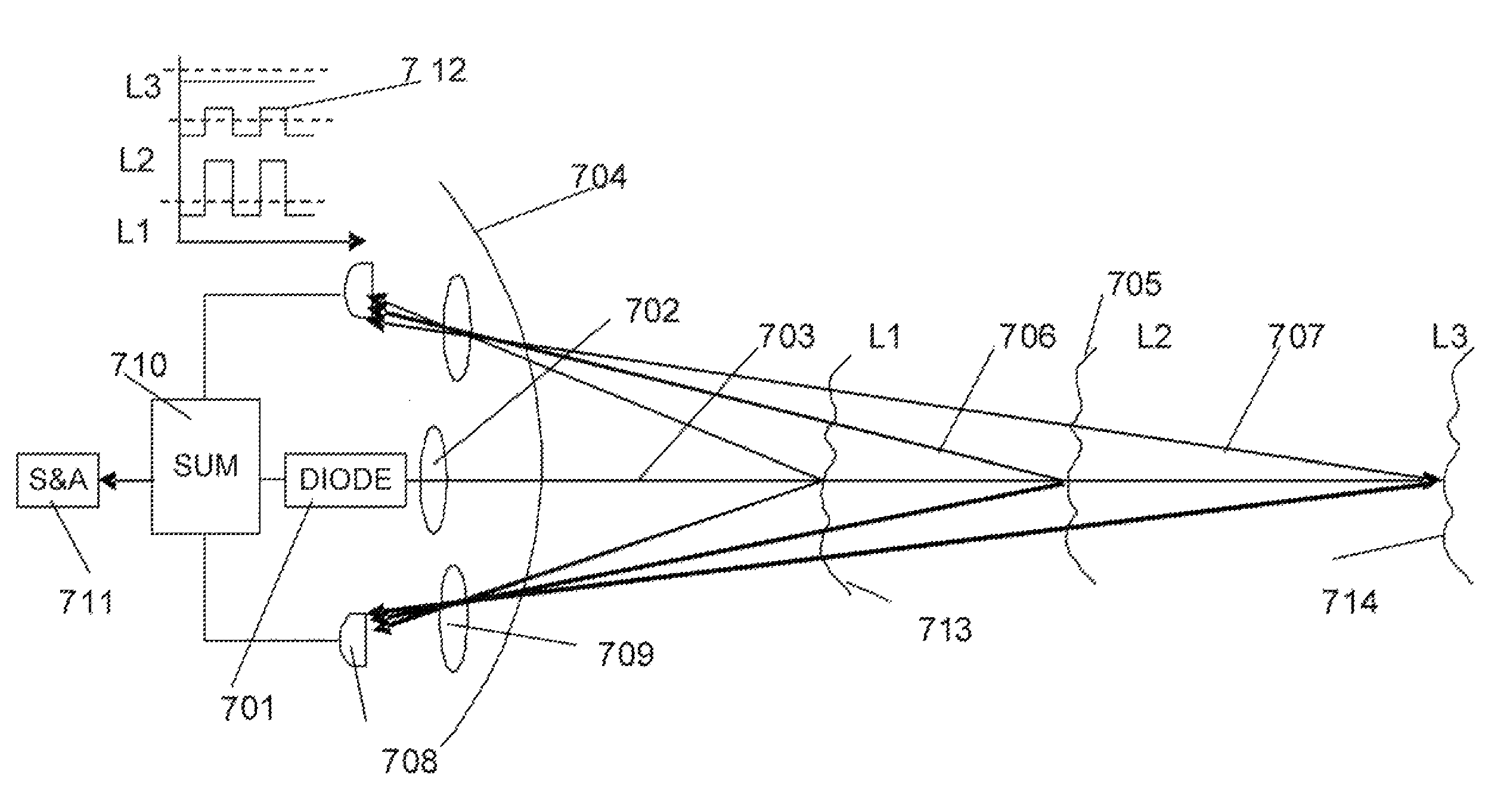
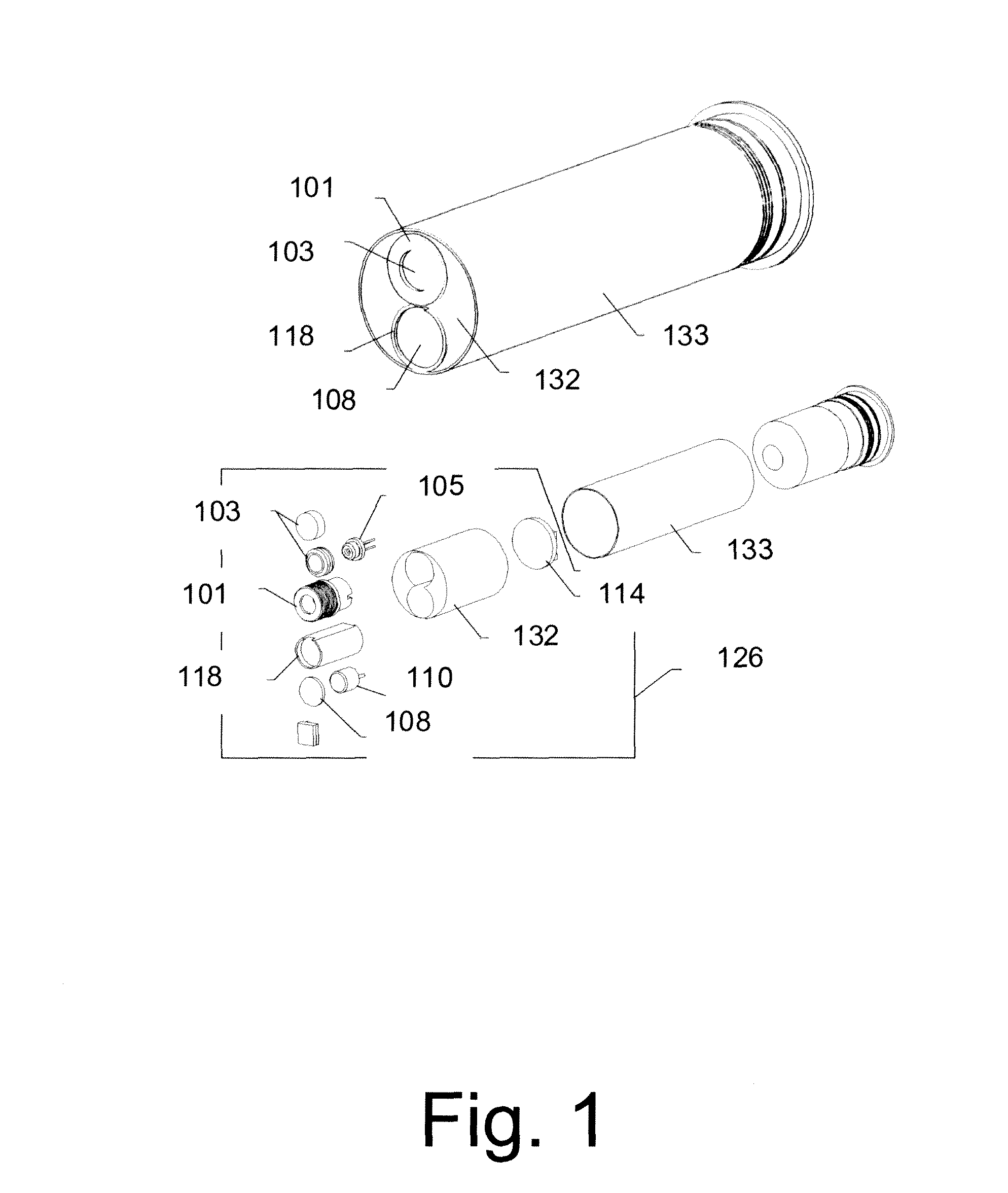
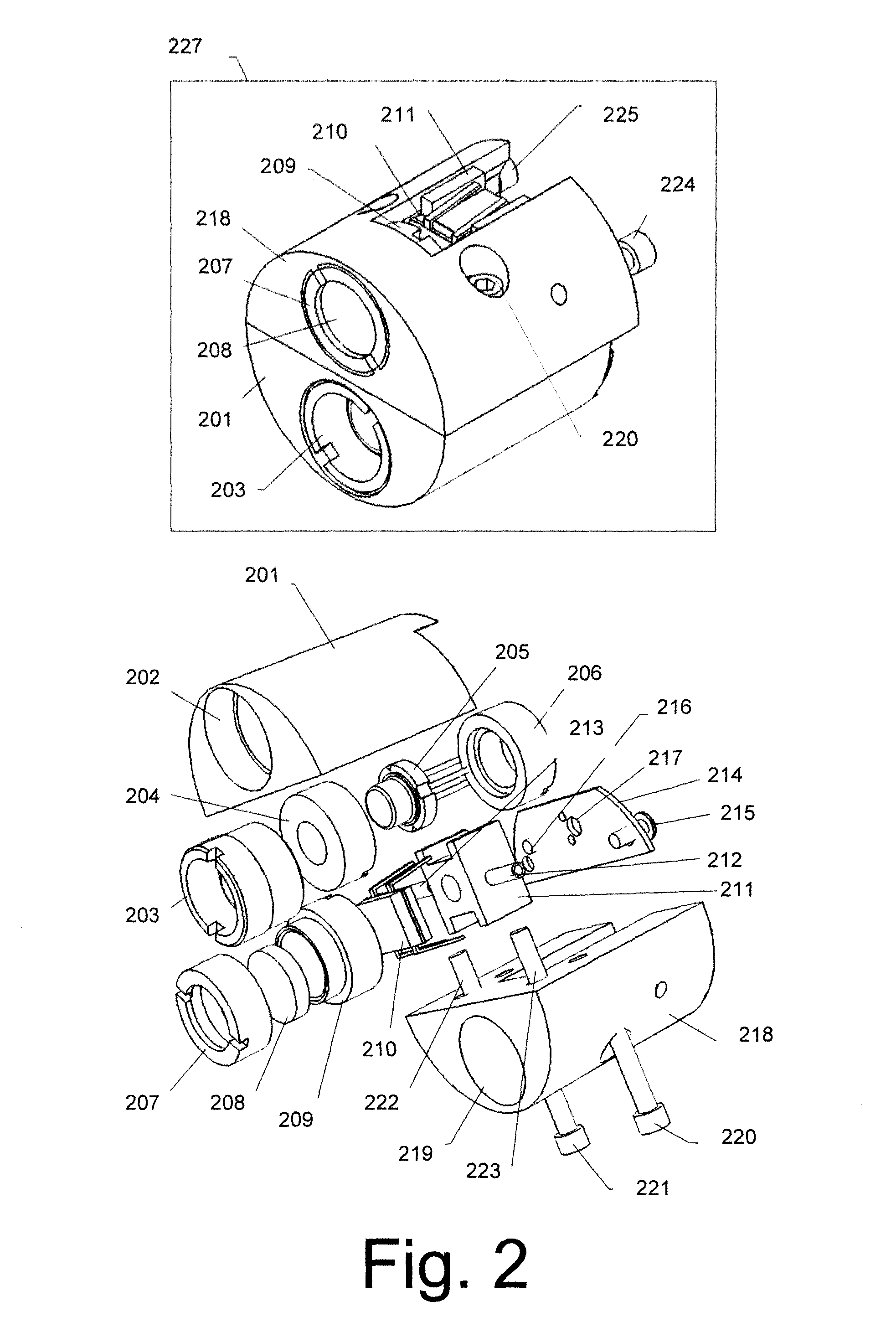
The invention is about attaching an optical impact system to fired munitions to improve their accuracy and reliability. It can be used in a variety of munitions and weapon systems, including non-lethal weapons and those with high lethality. The system works by sensing proximity to a target and preventing effects of countermeasures on false munitions termination. This can make the weapon resistant to optical countermeasures and improve its overall effectiveness.

Problems solved by technology

Unfortunately, currently all these weapon systems can only be used at relatively short distances (approximately 30 ft.).
Such short distances are not sufficient for the proper protection of law-enforcement agents from opposition force.
The limitation in the performance range of non-lethal weapon systems is generally associated with the kinetic energy of the bullet or projectile at the impact.
This energy is usually sufficient to penetrate a human tissue or to cause large blunt trauma, thus making the weapon system lethal.
More complex devices involve various types of range finders that measure the distance to a target.
Such type of weapon may be a lethal to bystanders in front of the target who intercept the projectile trajectory after the real target range has been transmitted to the projectile.
Acoustics sensors require relatively large emitting aperture that is not available on a small-caliber projectiles.
Both of these technologies allow for significant variability in the actual height of the airburst, potentially limiting effectiveness.
These types of fuzes are vulnerable to EMI, are bulky and heavy, have poor angular resolution (low target selectivity), and usually require some preset mechanism for activation at a given distance from the target.

Method used


Image

  • Optical impact control system
  • Optical impact control system
  • Optical impact control system

Examples


example 1

[0149]Assuming (SNR)=5 and τFAR=10−4, we obtain x=3.99, and z≅5−4=1; thus, Pd(1)=0.84, from Table 2.

example 2

[0150]Assuming the same (SNR)=5 but worse (FAR): τFAR=10−3, we obtain x=3.37 and z=1.63; thus, N(z)=0.8968 and Pd=0.95; i.e., we obtain better Pd-value.

From examples (1) and (2) we see that increasing of positive parameter, Pd, is at the expense of increasing of negative parameter, τFAR, and vice versa. This trade-off may be improved by increasing the SNR, as shown in example (3).

example 3

[0151]Assuming (SNR)=8 and τFAR=10−6, we obtain x=5.01 and z=3; thus, Pd=0.999. We see that by increasing (SNR)-value, we could obtain both excellent values of threshold probabilities: very low τFAR value (10−6) while preserving still high Pd-value (99.9%). Of course, for higher Pd-value; e.g., Pd>99.99%, we have z=4, and from (SNR)=8, we obtain x=4; thus τFAR=10−4; i.e., this negative probability will be larger than previous value (10−6); thus, confirming trade-off rule.

[0152]FIG. 25 illustrates a method of pulse detection using thresholding implemented in accordance with an embodiment of the invention. FIG. 25A illustrates a series of pulses transmitted by a light source in an optical proximity fuze. FIG. 25B illustrates the pulse 2502 received after transmission of pulse 2051. As illustrated, noise In results in distortion of the signal. A threshold IT 2503 may be established for the detector to register a detected pulse. Accordingly, pulse start time 2504 and end time 2505 may b...


PUM


Abstract

An optical impact system controls munitions termination through sensing proximity to a target and preventing effects of countermeasures on false munitions termination. Embodiments can be implemented on in a variety of munitions such as small and mid caliber that can be applicable in non-lethal weapons and in weapons of high lethality with airburst capability for example and in guided air-to-ground and cruise missiles. Embodiments can improve accuracy, reliability and lethality of munitions depending on its designation without modification in a weapon itself and make the weapon resistant to optical countermeasures.

Description

CROSS-REFERENCE TO RELATED APPLICATIONS[0001]This application claims the benefit of U.S. Provisional Application No. 61 / 265,270 filed Nov. 30, 2009, and which is hereby incorporated herein by reference in its entirety.TECHNICAL FIELD[0002]The present invention relates generally to optical detection devices, and more particularly, some embodiments relate to optical impact systems with optical countermeasure resistance.DESCRIPTION OF THE RELATED ART[0003]The law-enforcement community and U.S. military personnel involved in peacekeeping operations need a lightweight weapon that can be used in circumstances that do not require lethal force. A number of devices have been developed for these purposes, including a shotgun-size or larger caliber dedicated launcher to project a solid, soft projectile or various types of rubber bullets, to inject a tranquilizer, or stun the target. Unfortunately, currently all these weapon systems can only be used at relatively short distances (approximately ...

Claims


Application Information

Patent Timeline
Patent Type & Authority Patents(United States)
IPC IPC(8): F41G7/22F42B15/01F42B15/00F41G7/00
CPCF42C13/023
Inventor SANDOMIRSKY, SERGEYESTERKIN, VLADIMIRFORRESTER, THOMAS C.JANNSON, TOMASZKOSTRZEWSKI, ANDREWNAUMOV, ALEXANDERMA, NAIBINGRO, SOOKWANGSHNITSER, PAUL I.
Owner MERCURY MISSION SYST LLC
Learn More