
Rotary grinder control system and method

a control system and rotary grinder technology, applied in the field of rotary grinders, can solve the problems of reducing the cutting action of the rotor, affecting the quality of the grinding process, and the rotor motor can trip off, so as to reduce the size of the material

Active Publication Date: 2013-01-29
RAPID GRANULATOR INC
View PDF7 Cites 18 Cited by
  • Summary
  • Abstract
  • Description
  • Claims
  • Application Information

AI Technical Summary

Benefits of technology

The present invention is a control system for a rotary grinder that reduces material size for further processing or recycling. The system aims to enable the grinder to avoid over-current events and maximize grinding efficiency by programming or selecting various parameters based on the material being ground. The invention's technical effects include reducing rotor over-current events, enhancing grinding efficiency and controlling ram speed based on operator input.

Problems solved by technology

When the rotor becomes loaded down with too much material, the rotor motor can trip off due to blown fuses or thermal overloads.
Furthermore, in many instances the material being ground may begin to melt due to the heat buildup involved.
This problem is particularly acute when grinding various types of plastics, materials with low melting points, materials that tend to wrap themselves around the rotor, or materials with high coefficients of friction such as rubber.
Often the result is partially melted plastic clogging the cutters and screen grooves, thereby drastically diminishing the cutting action of the rotor.
Even when such clogging doesn't occur, if the material is fed towards the rotor too quickly the rotor motor must work too hard to grind the material thus decreasing the working life of the cutters and the motor.
In contradistinction, if the material is fed too slowly, the grinding operation uses more energy than necessary to efficiently grind the material or doesn't grind material at all, thereby reducing productivity and enhancing the time and expense of the grinding operation.

Method used


Image

  • Rotary grinder control system and method
  • Rotary grinder control system and method
  • Rotary grinder control system and method

Examples


Embodiment Construction

)

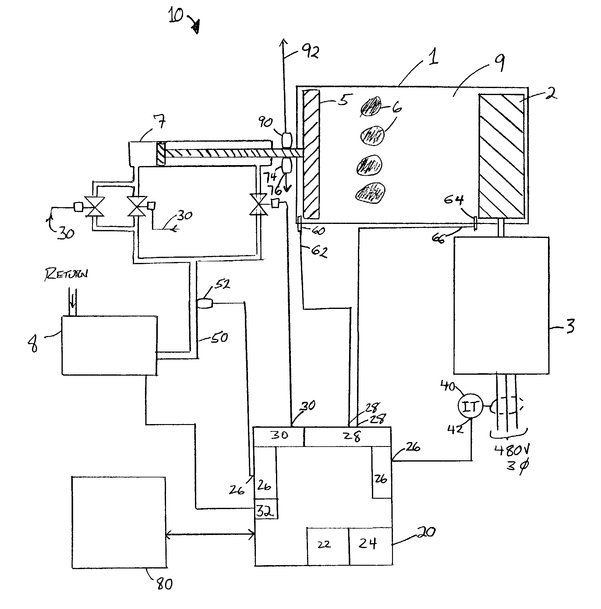
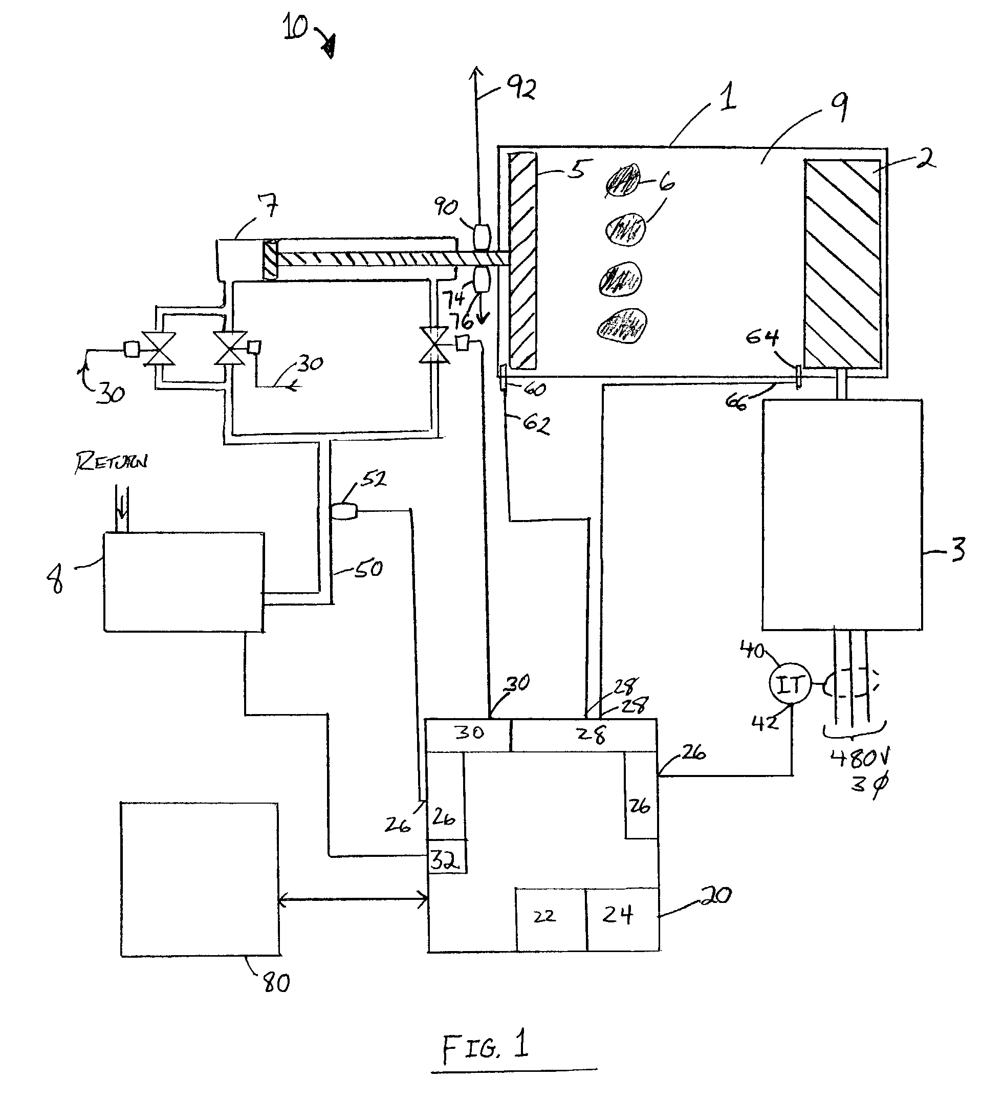
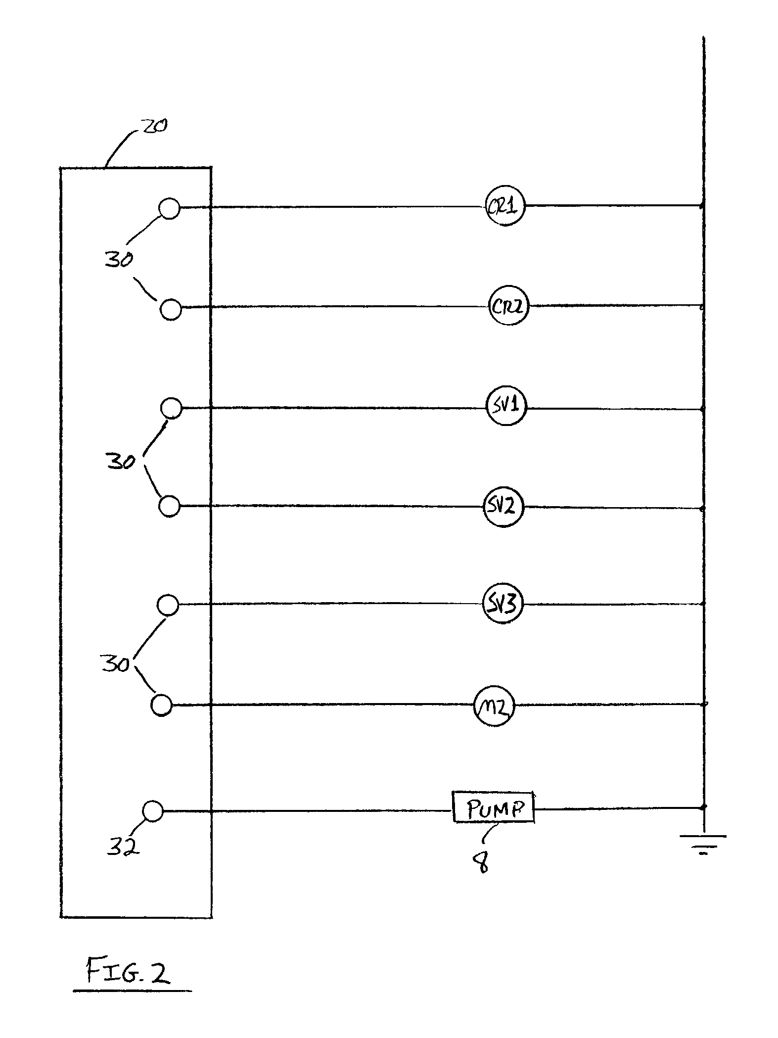
[0022]Referring now to drawing FIGS. 1,2 and 3 in a preferred constructed embodiment of the invention a control system 10 for a rotary grinder 1 having a cylindrical rotor 2 that is capable of rotation in both the clockwise and counterclockwise directions (or alternatively, forward and reverse) and a ram 5 that is capable of forward and backward motion (both towards and away from said rotor 2) comprises a central computer 20 having a plurality of analog and digital inputs and outputs and a plurality of sensors electrically connected thereto for controlling the grinder 1, as will be explained further below. A material to be ground 6 is fed into a space 9 between the rotor 2 and ram 5 from a hopper or bin prior to beginning the grinding operation.

[0023]The central computer 20 may be a conventional microcomputer having a processor 22 and a memory 24 associated therewith. The central computer 20 provides a plurality of both analog and digital inputs 26 and 28 respectively that accept a...


PUM


Abstract

The present invention relates to a control system for a rotary grinder. Rotary grinders control systems of the present invention are, for example, used to grind plastic or wood to reduce the size of the material to a desired size. Material to be ground is forced by an hydraulic ram toward a rotor having a plurality of cutters thereon. The control system is capable of controlling the grinding operation as a function of ram velocity and pressure as well as power consumption by the rotor.

Description

BACKGROUND OF THE INVENTION[0001]The present invention relates generally to a rotary grinder with an improved control system and more specifically to a control system capable of minimizing rotor over-current events while maximizing grinding efficiency for a rotary grinder having a rotor and a ram for feeding material into the rotor. Rotary grinders are used to grind a wide variety of materials including, but not limited to plastics, metals, woods, composite materials or rubber in various physical forms to reduce the size of the material to that suitable for further handling or processing. Material to be ground is usually placed inside a hopper which drops or feeds material into a space bounded by a ram at a first end and a rotor at a second end. The ram is then moved forward to force the material toward a driven rotor having a plurality of cutters (or teeth) thereon.[0002]Furthermore, a grooved screen, or a plurality thereof, may be employed at an outlet proximate the rotor wherein ...

Claims


Application Information

Patent Timeline
IPC IPC(8): B02C23/00B02C4/32
CPCB02C13/286B02C18/22B02C18/2233B02C23/02B02C25/00
Inventor SOTSKY, GEORGE R.
Owner RAPID GRANULATOR INC
Learn More