
Polarizer and waveguide antenna apparatus using the same

a technology of waveguide antenna and waveguide antenna, which is applied in the direction of antennas, waveguide type devices, basic electric elements, etc., can solve the problems of narrow operating frequency of traditional polarizers, inability to meet the requirements of industrial applicability, and narrow bandwidth of traditional polarizer operating frequency

Active Publication Date: 2013-01-15
MICROELECTRONICS TECH INC
View PDF2 Cites 21 Cited by
  • Summary
  • Abstract
  • Description
  • Claims
  • Application Information

AI Technical Summary

Benefits of technology

The design enhances signal isolation and reduces cavity resonance, ensuring better signal quality across a broader frequency range, including frequencies above the X-band.

Problems solved by technology

However, traditional polarizers have several drawbacks.
First, the bandwidth of the operating frequency of traditional polarizers is narrow, not satisfying the requirements of industrial applicability.
Second, the square cross section of a traditional polarizer may easily exhibit cavity resonance phenomenon, and such resonance phenomenon may occur near the in-band frequency, negatively affecting signal quality.
Third, when the operating frequency is greater than the X-band frequency (10 GHz), traditional polarizers cannot ensure the proper signal isolation between ports.
Thus, traditional polarizers still have many drawbacks, and development of a new polarizer is needed.

Method used


Image

  • Polarizer and waveguide antenna apparatus using the same
  • Polarizer and waveguide antenna apparatus using the same
  • Polarizer and waveguide antenna apparatus using the same

Examples


Embodiment Construction

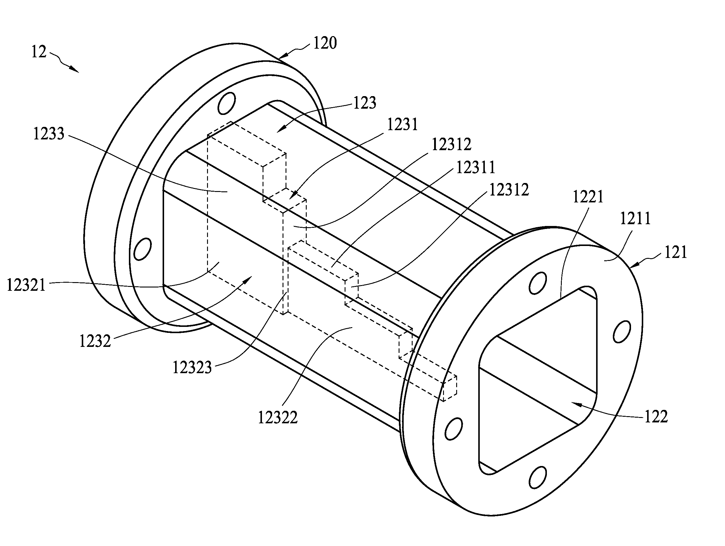
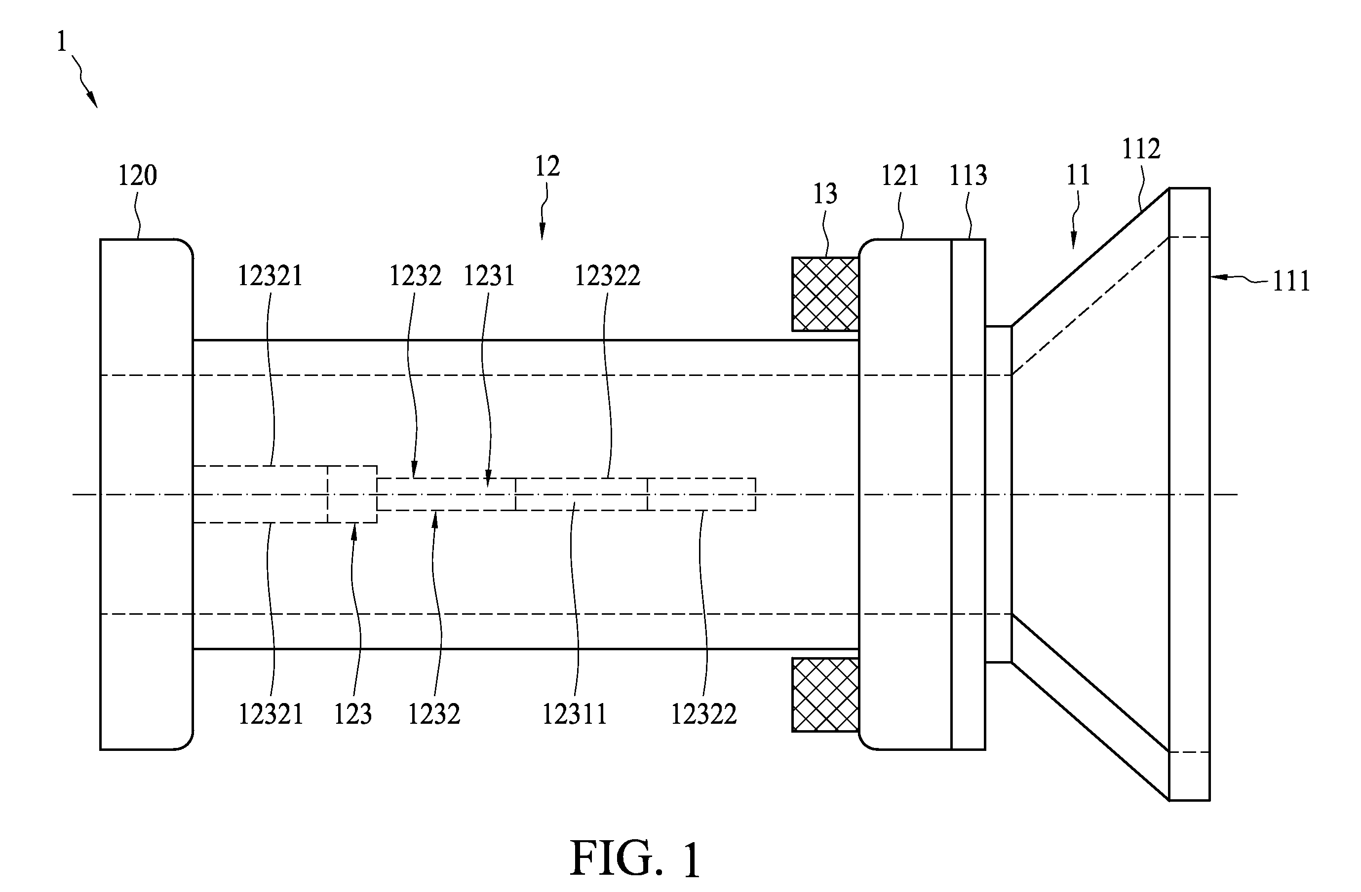
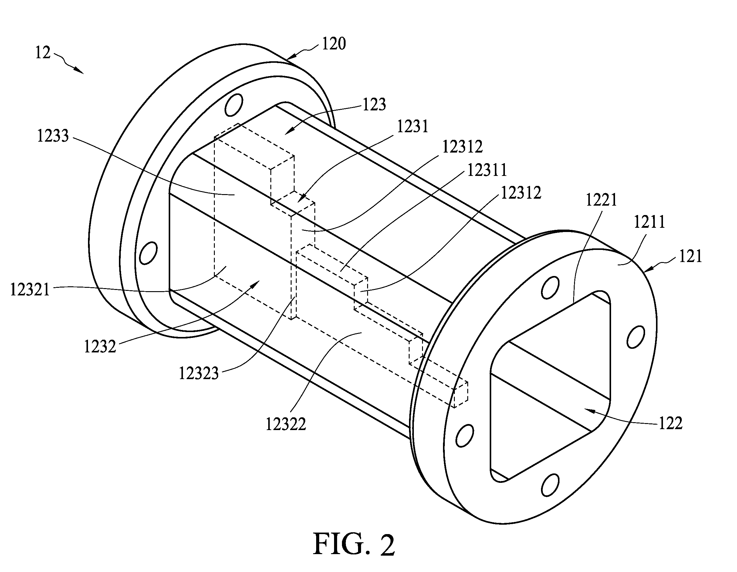
[0022]FIG. 1 is a side view showing a waveguide antenna apparatus 1 according to one embodiment of the present invention. A waveguide antenna apparatus 1 of the present invention may comprise a feed horn 11 and a polarizer 12. The feed horn 11 comprises an aperture 111, a flared section 112, and a fixing portion 113. The aperture 111 is configured to face toward a dish antenna for guiding microwave energy in and out. The flared section 112 defines the aperture 111, connecting to the fixing portion 113. The polarizer 12 may have two end portions. Each end portion can be disposed with a fixed portion 120 or 121 so that the fixing portion 113 of the feed horn 11 can be fixed to the fixed portion 121 of the polarizer 12 using fasteners 13.

[0023]Referring to FIGS. 1 and 2, the polarizer 12 may comprise a waveguide channel 122 penetrating through the polarizer 12, forming two openings respectively on the end surfaces 1211 of the two fixed portions 120 and 121. The cross section of the wav...


PUM


Abstract

A polarizer includes a waveguide channel having a substantially square cross section and a septum disposed within the waveguide channel. The septum includes a stepped edge and two opposite stepped surfaces. The stepped surfaces are sectionally recessed toward each other along the direction pointing toward the interior of the waveguide channel, wherein the number of the steps of the stepped surface is greater than two, but smaller than the number of the steps of the stepped edge. In one embodiment, the square cross section may include a plurality of rounded corners and a plurality of edges extending correspondingly between the rounded corners, wherein the ratio of the radius of the rounded corner to the distance between two opposite edges is in a range of from 0.05 to 0.3.

Description

BACKGROUND OF THE INVENTION[0001]1. Field of the Invention[0002]The present invention relates to a waveguide antenna apparatus and a polarizer, and relates more particularly to a polarizer having a stepped septum and a waveguide antenna apparatus using the same.[0003]2. Description of the Related Art[0004]In a microwave antenna system, a polarizer is utilized to convert a linearly polarized magnetic field to a circularly polarized magnetic field, or vice versa. Generally, different types of polarizer can be used in a microwave antenna system, in which a septum polarizer is one of the most popular.[0005]A septum polarizer includes a waveguide. The waveguide may have an internal channel, which may have a cross section with a circular shape or a square shape. The metal septum is inserted into the channel in a direction along the longitudinal axis of the waveguide, dividing the channel into two equal sub-channels. An electromagnetic wave may be decomposed, by the septum, into two equal ...

Claims


Application Information

Patent Timeline
Patent Type & Authority Patents(United States)
IPC IPC(8): H01Q19/00H01Q13/00
CPCH01Q13/0241H01P1/173
Inventor LIN, CHIH JUNGSUNG, HSIANG HAO
Owner MICROELECTRONICS TECH INC
Learn More