Eureka AIR delivers breakthrough ideas for toughest innovation challenges, trusted by R&D personnel around the world.

Checking method and electronic circuit for the secure serial transmission of data

a technology of electronic circuit and serial transmission, applied in the field of checking method, can solve problems such as undesirable change to the usual polynomial, and achieve the effect of reducing residual errors

Active Publication Date: 2013-01-08
CONTINENTAL TEVES AG & CO OHG
View PDF19 Cites 13 Cited by
  • Summary
  • Abstract
  • Description
  • Claims
  • Application Information

AI Technical Summary

Benefits of technology

[0009]An object of the present invention is likewise to reduce the residual error for serial data transmissions protected by means of CRC check data in comparison with the prior art.
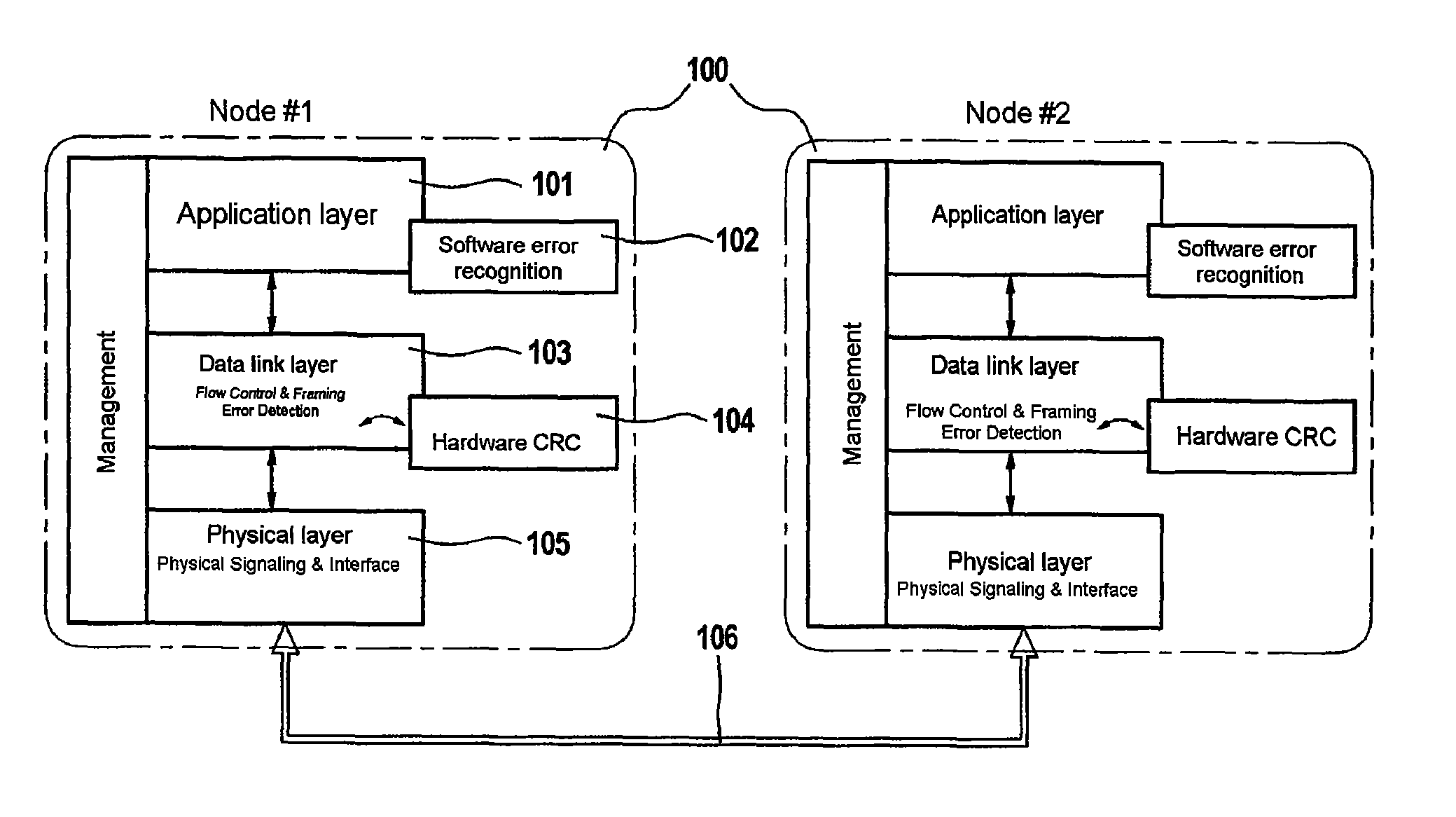
[0012]Preferably, the region of the receiver contains not only the error recognition hardware means but also error recognition software means which are used to additionally check the received data. This method step can be used to reduce the residual error mentioned further above and hence to increase the level of security on the serial connection. By way of example, the software means is a software program which carries out an error recognition method which can be used to lower the error rate and hence to further increase the level of security for the transmission at least theoretically.
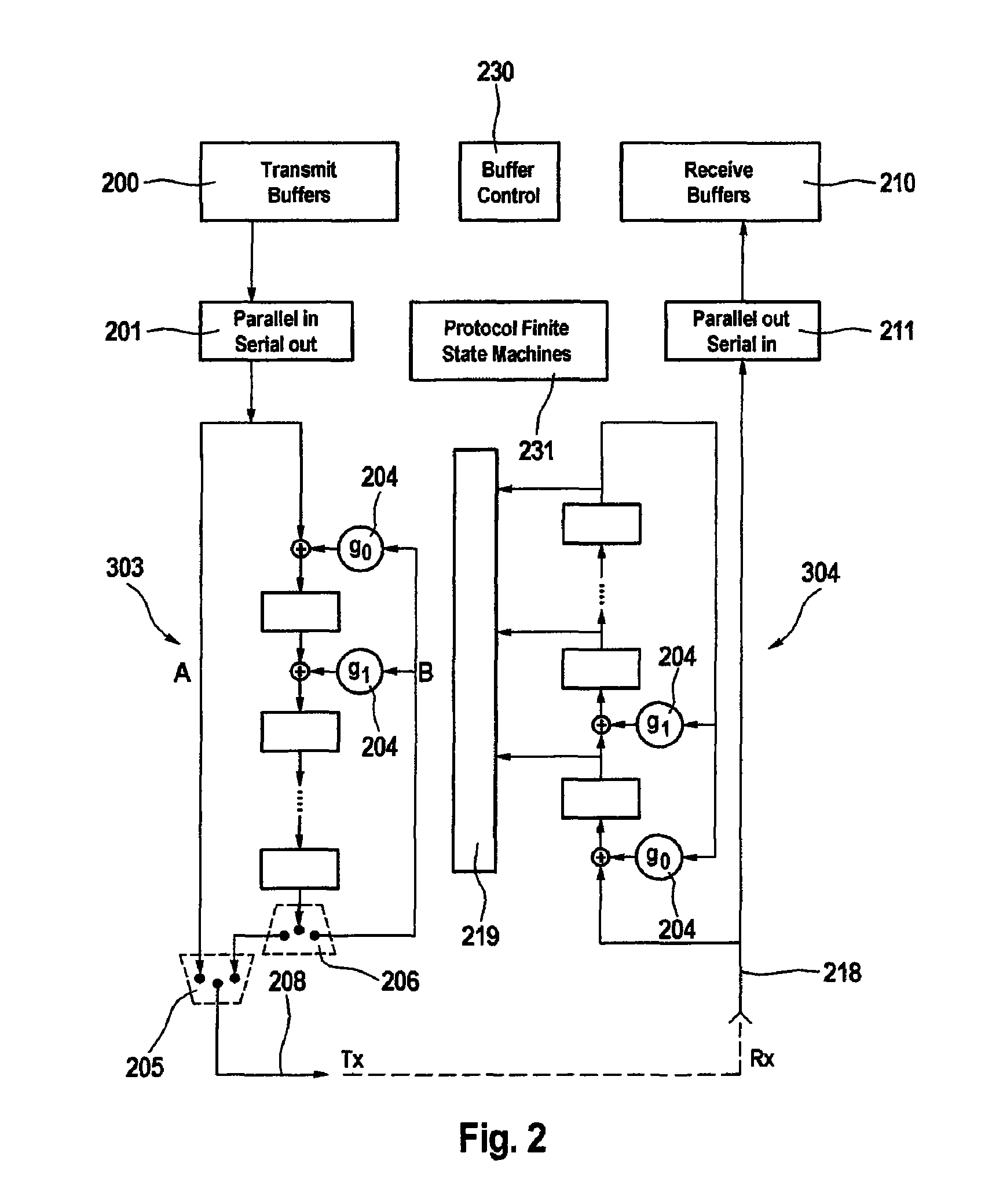
[0014]On the basis of the method according to aspects of the invention, a data stream to be transmitted can be specifically provided with errors which cannot be recognized by the hardware provided for recognizing errors (for example CRC recognition hardware) at the receiver end. In this way, it is possible, inter alia, to determine the error recognition rate of an additional piece of error recognition software quantitatively. The specific stimulation of such unrecognizable errors also allows the correct operation of the receiver-end error recognition hardware to be checked.
[0015]In line with a further preferred embodiment, the method according to aspects of the invention also involves the stimulation of specific errors which, as a result of the recognition hardware in the receiver, are certain to cause an error-assuming error-free transmission. This is a reliable way of recognizing errors in the receiver-end error-test hardware.

Problems solved by technology

Although it would likewise be possible to increase the data transmission security by using a more complex CRC polynomial, this would result in an undesirable change to the usual polynomial.

Method used


Image

  • Checking method and electronic circuit for the secure serial transmission of data
  • Checking method and electronic circuit for the secure serial transmission of data
  • Checking method and electronic circuit for the secure serial transmission of data

Examples


Embodiment Construction

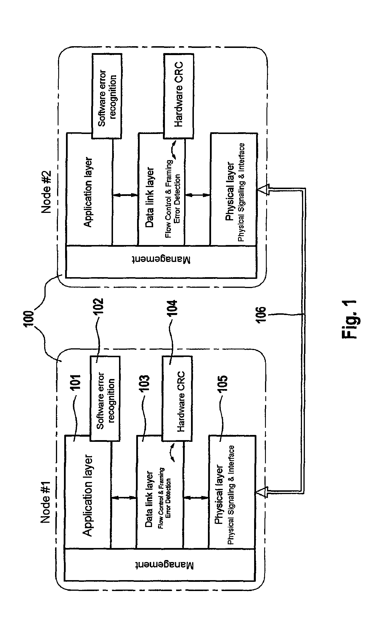
[0028]FIG. 1 shows a schematic block diagram of protocol layers featuring bus nodes 100 which communicate using a standardized serial bus system 106. A bus node comprising a transmitter and a receiver (transceiver) usually comprises a micro-controller and a communication controller for communication. In this case, the communication controller may be integrated in the micro-controller. A node 100 can be assigned three protocol layers:[0029]application layer 101, data link layer 103 and physical layer 105 for transmitting the bits.

[0030]The application layer 101 is in the form of a piece of software, whilst the data link layer 103 and the bit transmission layer 105 are depicted in hardware. The CRC calculation and checking take place in the data link layer 103 and are handled in the CRC hardware module 104. A suitably selected CRC polynomial can be used by the CRC hardware module 104 to recognize errors which occur during data transmission on the bus 106 with a high degree of coverage...


PUM


Abstract

A checking method in which serial data protected by check data are transmitted via a serial data bus from a transmitter to a receiver, the receiver then conditions the data and compares them with the transmitted check data in order to recognize transmission errors, wherein the transmitter bases the production of the check data and the receiver bases the conditioning of the data on the same check data formation method, wherein the check data formation / conditioning is performed using error recognition hardware, wherein the region of the receiver contains not only the error recognition hardware but also error recognition software which are used to additionally check the received data, and wherein also an error in the transmitted data and / or check data is caused by a transmitter-end error stimulation. A transmission and reception circuit for carrying out the above method and also the use thereof is also disclosed.

Description

CROSS REFERENCE TO RELATED APPLICATIONS[0001]This application is the U.S. national phase application of PCT International Application No. PCT / EP2008 / 055934, filed May 15, 2008, which claims priority to German Patent Application No. 10 2007 028 766.8, filed Jun. 22, 2007, the content of such applications being incorporated by reference herein.BACKGROUND OF THE INVENTION[0002]1. Field of the Invention[0003]The invention relates to a checking method in which serial data protected by means of check data are transmitted via a serial data bus from a transmitter to a receiver, to an electronic transmission or reception circuit or to a transceiver, which comprises a transmitter and a receiver having serial data transmission means and to the use thereof.[0004]2. Description of the Related Art[0005]Serial bus systems, such as “Controller Area Network” (CAN), Flexray(R) or “Serial Peripheral Interface” (SPI), are already used in motor vehicle electronics for the purpose of networking electroni...

Claims


Application Information

Patent Timeline
Patent Type & Authority Patents(United States)
IPC IPC(8): G06F11/00
CPCH04L1/0061H04L1/24H04L2001/0094
Inventor KABULEPA, LUKUSA DIDIERTRASKOV, ADRIAN
Owner CONTINENTAL TEVES AG & CO OHG
Why Eureka
Eureka Blog
Learn More