
Display device and manufacturing method of display device

a technology of display device and manufacturing method, which is applied in the manufacture of electrode systems, electric discharge tubes/lamps, instruments, etc., can solve the problems of defective linear area, inability to properly transmit signals beyond the short-circuited portion of the source bus line, etc., and achieve the effect of increasing resistan

Inactive Publication Date: 2013-01-08
SHARP KK
View PDF28 Cites 0 Cited by
  • Summary
  • Abstract
  • Description
  • Claims
  • Application Information

AI Technical Summary

Benefits of technology

The present display device is designed to prevent display performance degradation caused by leakage or other faults in the conductive layer. This is achieved by cutting off a portion of the conductive layer, starting at an end area of a slit portion provided as a wider area than the medial area. The slit width is set to be smaller at the medial area to avoid increase of resistance of the conductive layer. The technical effect is a highly reliable conductive feature that ensures a high-quality display device.

Problems solved by technology

In the display device, when a leak has occurred between intersecting wiring lines such as a source bus line and a gate bus line, a signal cannot be transmitted properly beyond the short-circuited portion of the source bus line.
This will cause a linear area that includes defective display (i.e., line defect).

Method used


Image

  • Display device and manufacturing method of display device
  • Display device and manufacturing method of display device
  • Display device and manufacturing method of display device

Examples


embodiment 2

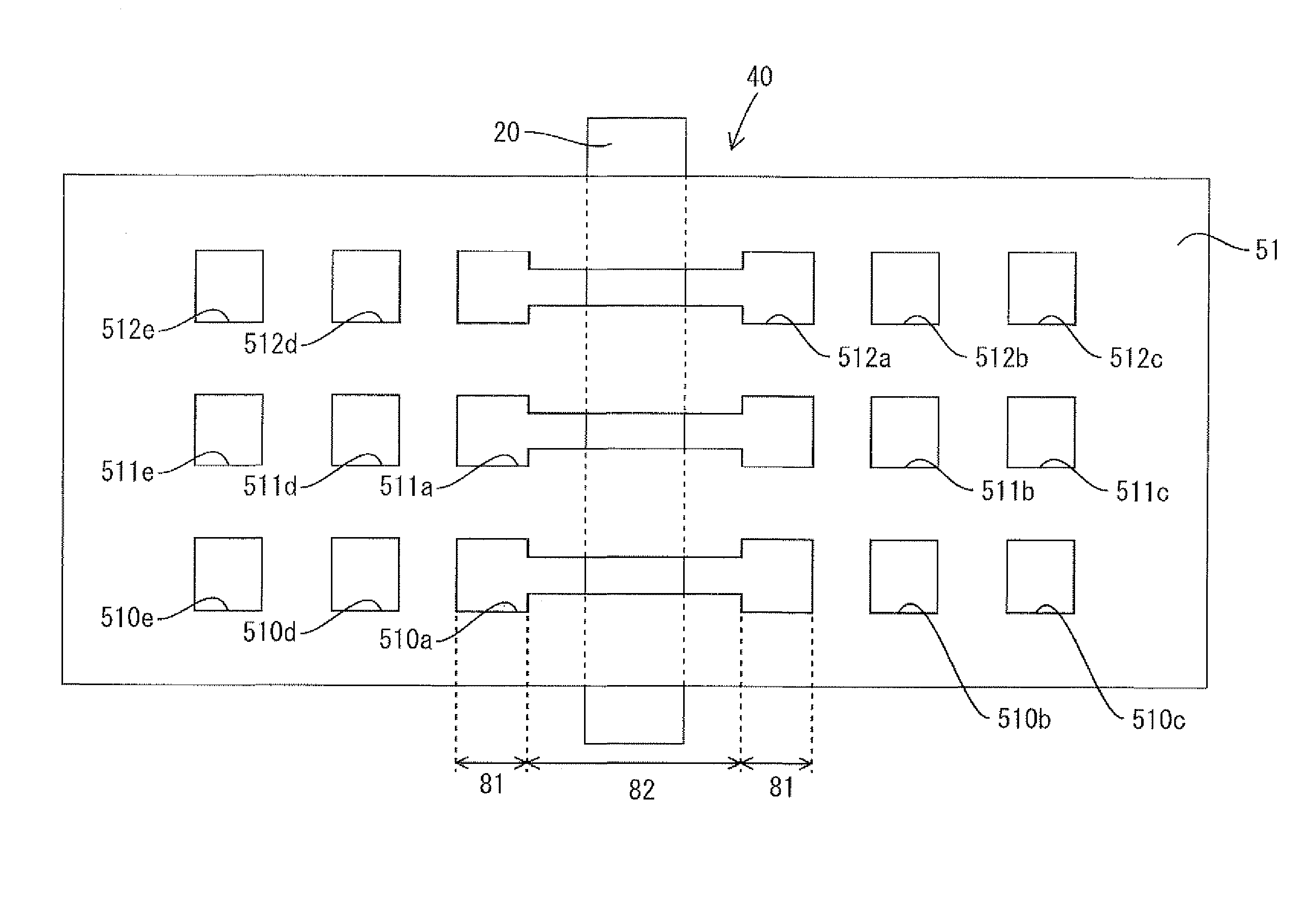
[0065]An embodiment 2 of the present invention will be explained with reference to FIGS. 11 and 12. The difference from the above embodiment 1 is that cutout portions are provided at a predetermined distance from respective slit portions. The other constructions are similar to the above embodiment. Therefore, the same parts as the above embodiment are designated by the same symbols, and redundant explanations are omitted.

[0066]FIG. 11 is a partially-enlarged plan view of a liquid crystal display device according to the present embodiment. FIG. 12 is an explanatory diagram showing the operational effects of the liquid crystal display device according to the present embodiment.

[0067]Referring to FIG. 11, in each crossover section 40 (or overlap section) at which a storage capacitor line (or first conductive layer) 20 and a peripheral wiring line (or second conductive layer) 51 intersect each other, fault repair slit portions 510a, 511a, 512a and the like (hereinafter sometimes collect...


PUM


Abstract

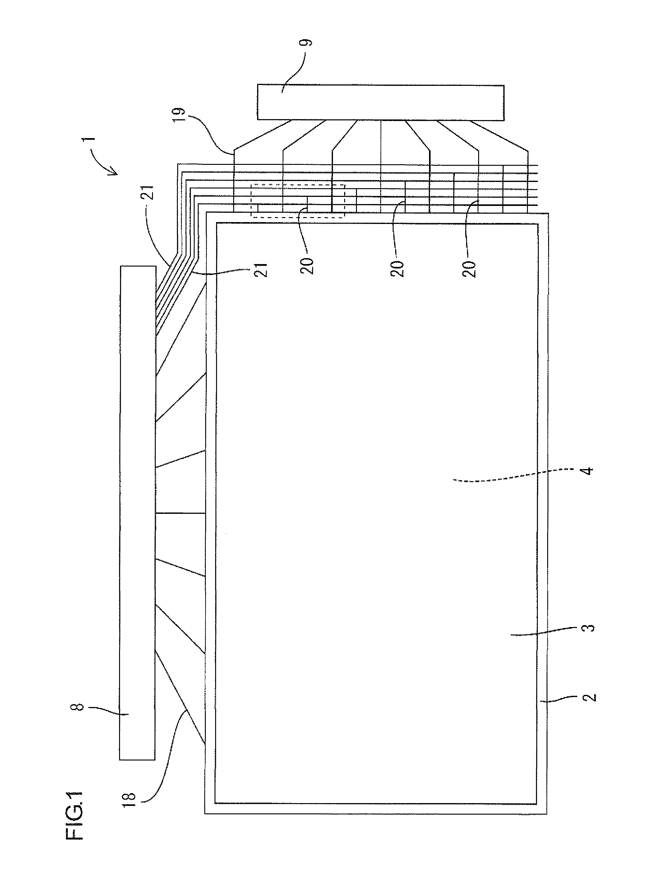
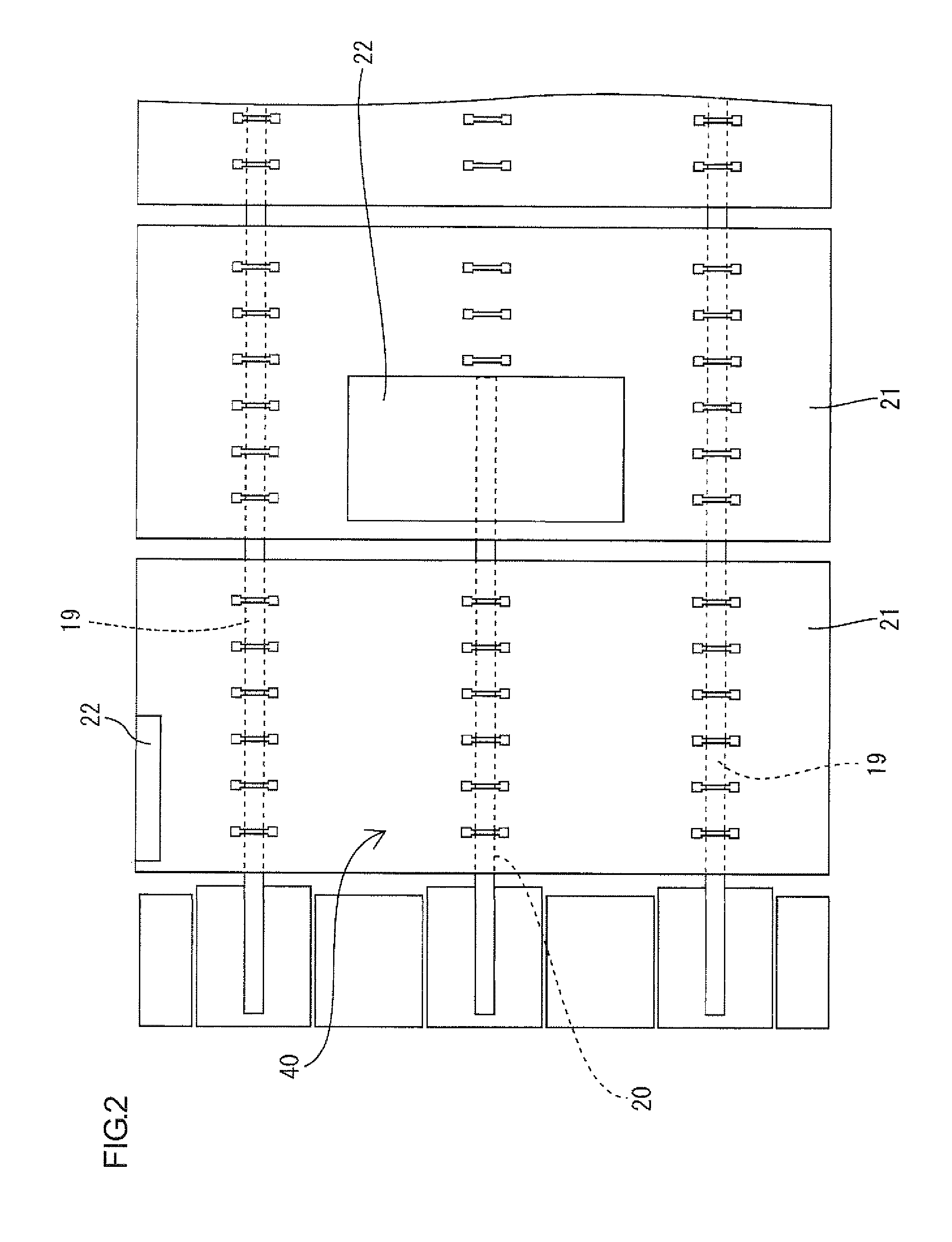
A display device 1 of the present invention includes a first conductive layer 20 and a second conductive layer 21 arranged across an insulating layer 24 from the first conductive layer 20. An overlap section 40 at which the first conductive layer 20 and the second conductive layer 21 overlap each other is provided. At least one of the first conductive layer 20 and the second conductive layer 21 includes a slit portion 210a that is arranged in the overlap section 40. The width of the slit portion 210a is set to be smaller at a medial area 82 except both end areas 81 of the slit portion 210a, than at the both end areas 81.

Description

[0001]This application is the U.S. national phase of International Application No. PCT / JP2007 / 073307 filed 3 Dec. 2007, which designated the U.S. and claims priority to JP Application No. 2007-113157 filed 23 Apr. 2007, the entire contents of each of which are hereby incorporated by reference.TECHNICAL FIELD[0002]The present invention relates to a display device and a manufacturing method of a display device.BACKGROUND ART[0003]A display device, such as a liquid crystal display device, an EL display device or a plasma display device, is conventionally known, in which pixel electrodes are arranged in a matrix on a transparent substrate. A voltage is applied individually to each pixel electrode in order to form an image. An active matrix driving method is known as a driving method for the display device. In the active matrix display device, gate bus lines (or scanning lines) and source bus lines (or signal lines) are arranged in a grid pattern on the transparent substrate, while switc...

Claims


Application Information

Patent Timeline
IPC IPC(8): G02F1/13
CPCG02F1/136259G02F2001/136263G02F1/136263
Inventor NAKAGAWA, HIDETOSHI
Owner SHARP KK
Learn More