
Elevator element for driving or reversing an elevator suspension means in an elevator system

a technology of elevator suspension means and elevators, which is applied in the direction of hoisting equipments, gearing, manufacturing tools, etc., to achieve the effect of optimizing wear behavior

Active Publication Date: 2013-01-08
INVENTIO AG
View PDF11 Cites 9 Cited by
  • Summary
  • Abstract
  • Description
  • Claims
  • Application Information

AI Technical Summary

Benefits of technology

[0005]The underlying purpose of the present invention is to create an elevator element of the type described above in which with the lowest possible manufacturing outlay an optimization of the wear behavior between elevator element and elevator suspension means can be attained.
[0006]According to the present invention, the purpose is fulfilled by means of an elevator element which is manufactured in such manner that the arithmetic mean of the roughness value of its at least one contact surface that is measured in the circumferential direction of the elevator element, and the mean roughness value of its contact surface measured in the axial direction of the elevator element, are different. The advantage of the solution according to the present invention is that—with lower roughness in the circumferential direction for the purpose of minimizing wear—the manufacturing costs of the elevator element relative to an elevator element with equal roughness in both directions can be reduced. Furthermore—in particular when using flat belts as elevator suspension means—an increased roughness of the contact surfaces in the axial direction of the elevator element can positively affect the lateral guidance of the elevator suspension means on the elevator element.
[0007]Furthermore, the objective of an elevator element according to the present invention is fulfilled in which the arithmetic mean roughness value of the contact surface measured in the circumferential direction of the elevator element is less than 1 micrometer, preferably 0.1 to 0.8 micrometer, particularly preferably 0.2 to 0.6 micrometer. One of the advantages of contact surfaces with a roughness according to these specifications is the low wear of the elevator suspension means as well as of the contact surfaces of the elevator element itself. A further advantage is that the maximum traction force between the elevator element and the elevator suspension means is relatively exactly limited, which is particularly important in the operating situation in which the elevator suspension means should slip relative to the elevator element during a limited time. Such an operating situation can arise, for example, when as a result of a control fault the elevator car or the counterweight strikes its lower path limits, or when the elevator car or the counterweight is blocked along its travel path for other reasons.

Problems solved by technology

Such an operating situation can arise, for example, when as a result of a control fault the elevator car or the counterweight strikes its lower path limits, or when the elevator car or the counterweight is blocked along its travel path for other reasons.

Method used


Image

  • Elevator element for driving or reversing an elevator suspension means in an elevator system
  • Elevator element for driving or reversing an elevator suspension means in an elevator system

Examples


Embodiment Construction

[0019]The U.S. provisional patent application Ser. No. 60 / 945,169 filed Jun. 20, 2007 is hereby incorporated herein by reference.

[0020]The following detailed description and appended drawings describe and illustrate various exemplary embodiments of the invention. The description and drawings serve to enable one skilled in the art to make and use the invention, and are not intended to limit the scope of the invention in any manner. In respect of the methods disclosed, the steps presented are exemplary in nature, and thus, the order of the steps is not necessary or critical.

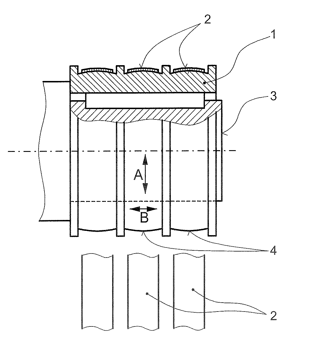
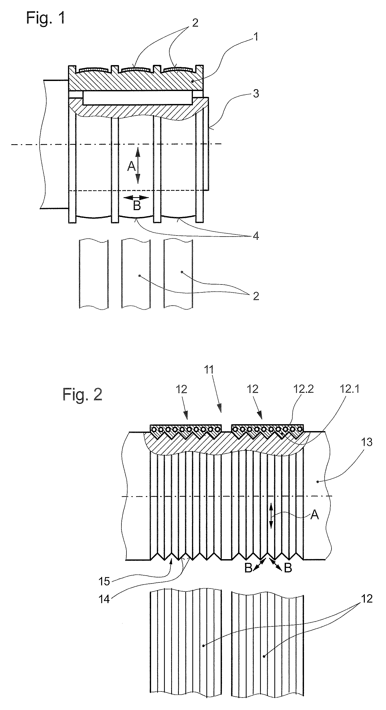
[0021]FIG. 1 shows an elevator element 1 according to the present invention for driving and / or reversing an elevator suspension means 2 in an elevator system, wherein the elevator element 1 is present in the form of a traction sheave that is fixed on a drive shaft 3 of a drive unit (not shown). This elevator element 1 comprises three contact surfaces 4 which, during elevator operation, interact with three elevator ...


PUM

PropertyMeasurementUnit
arithmetic mean roughnessaaaaaaaaaa
roughnessaaaaaaaaaa

Abstract

In an elevator element for driving or reversing an elevator suspension device in an elevator system, that interacts with an elevator suspension device, the arithmetic mean of the roughness value of the contact surface measured in the circumferential direction of the elevator element, and the mean roughness value of the contact surface measured in the axial direction of the elevator element, are different. The arithmetic mean roughness value of the contact surface measured in the circumferential direction of the elevator element is less than 1 micrometer.

Description

CROSS-REFERENCE TO RELATED APPLICATION[0001]This application claims the benefit of U.S. provisional patent application Ser. No. 60 / 945,169 filed Jun. 20, 2007.FIELD OF THE INVENTION[0002]The present invention relates to an elevator element for driving and / or reversing an elevator suspension means or device in an elevator system and a method for manufacturing such an elevator element. An elevator element according to the present invention has at least one contact surface via which the elevator element interacts with the elevator suspension means for the purpose of transferring a driving force from a drive unit to the elevator suspension means or to reverse such an elevator suspension means within the elevator system. Preferably, such an elevator element is executed in the form of a traction sheave or of a reversing pulley. In the present context, “elevator suspension means” is to be understood as a flexible tension element, for example a rope or a flat-belt type tension element with ...

Claims


Application Information

Patent Timeline
Patent Type & Authority Patents(United States)
IPC IPC(8): B66B11/08B66D1/00F16H27/02F16H55/36F16H55/48
CPCB66B15/04Y10T74/18848Y10T29/49982
Inventor BLOCHLE, HANSACH, ERNST
Owner INVENTIO AG
Learn More