Elimination of shrinkage cavity in cast ingots

a technology of shrinkage cavity and cast ingot, which is applied in the field of partial or complete elimination of shrinkage cavity in cast ingot, can solve the problems of insufficient removal of excess metal, defect known as “alligatoring” and other problems, and achieve the effect of avoiding metal spillag

Active Publication Date: 2013-01-08
NOVELIS INC
View PDF5 Cites 12 Cited by
  • Summary
  • Abstract
  • Description
  • Claims
  • Application Information

AI Technical Summary

Benefits of technology

[0015]The repeated filling steps tend to produce an ingot having a stepped elevated “crown” at the upper surface, especially when over-filling is carried out. However, as the ingot head contracts, the metal in the head may solidify in a way that forms a stepped crown shape even when mere partial filling is carried out.
[0017]Another exemplary embodiment provides a method of eliminating a shrinkage cavity in a metal ingot cast by direct chill casting. The method comprises casting a metal ingot by introducing molten metal into a direct chill casting mold from a spout to form an upright ingot having an upper surface at a predetermined height. Upon completion of the casting, molten metal flow through the spout is terminated while sufficient heat in metal within and supplying the spout is maintained to keep the metal molten for subsequent delivery through the spout. A partial shrinkage cavity is allowed to form in the upper surface of the ingot as metal of the ingot contracts, and then the partial shrinkage cavity is over-filled while all or significant spillage of molten metal from the partial cavity is avoided, and then the flow of metal through the spout is terminated. The steps of allowing a partial shrinkage cavity to form in the upper surface, then over-filling the partial shrinkage cavity with molten metal from the spout, followed by termination of the flow of metal through the spout, are repeated at least once. The repetition of the steps is then terminated when no further shrinkage or contraction of the metal of the ingot causes any part of the upper surface to shrink or contract below the predetermined height. The spout is then removed from contact with molten metal of the ingot and all parts of the ingot are allowed to cool to a temperature at which the metal is fully solid.

Problems solved by technology

While the metal cut off in this way may be recycled, the procedure is nevertheless costly and inefficient.
If the cavity is not removed in this way, a defect known as “alligatoring” may occur during rolling of the ingot.
The use of such “hot tops” is not convenient for the direct chill casting process and again it may result in the need for the removal of an excess of metal from the upper part of the ingot as the molten reservoir itself cools and solidifies in contact with the ingot proper.
However, this solution is not generally possible in conventional direct chill casting apparatus because molten metal in the channels and spouts above the mold tends to solidify once the main casting operation has been terminated, and anyway the kind of precise control that would allow filling of the cavity while avoiding spillage has not generally been possible.

Method used


Image

  • Elimination of shrinkage cavity in cast ingots
  • Elimination of shrinkage cavity in cast ingots
  • Elimination of shrinkage cavity in cast ingots

Examples


example 1

[0054]Aluminum alloy ingots were cast in a tandem mold direct chill casting apparatus of the kind shown in plan view in FIG. 6 of the accompanying drawings.

[0055]Prior to the cast, heated control pins were inserted into the spouts and powered at 1000 watts each (full power). At 100 mm into the cast, the power was reduced to 25% (250 watts). At a cast length of 200 mm before the end of the cast (stoppage of bottom block), the power to the control pin heaters was increased from 250 watts to 1000 watts to ensure that the metal in the spouts stayed molten before the end of cast filling process.

[0056]The end-of-cast sequence was initiated manually when the desired length of the cast was reached. This caused the furnace to tilt back and the control pins to close the spouts. The bottom block continued to move down. As the furnace began to tilt back, a dam was placed manually into the distribution launder to prevent metal flowing back to the furnace, thus maintaining a sufficient volume of ...

example 2

[0062]A casting operation of the kind described in Example 1 was carried out, again in the apparatus of the general kind shown in FIG. 6, but with unheated control pins As casting proceeded, the heat of the molten metal kept the spouts and pins sufficiently hot to avoid freezing and blockage. The temperature of the molten metal supplied to the casting apparatus was sufficiently elevated to avoid freezing caused by heat losses in the apparatus. The details of the casting procedure are as follows.

[0063]Casting was carried out in a mold table holding five casting molds, but the center mold (position number 3) was not used so only four ingots were cast simultaneously. In fact, the ingots cast in this way were stub ingots, i.e. ingots of less than normal height. Automation changes were added to the PLC program to modify the timing of the trough tilt and metal level control pins. At end-of-cast, the furnace was tilted back as normal. When the metal level in the trough dropped to a certain...

example 3

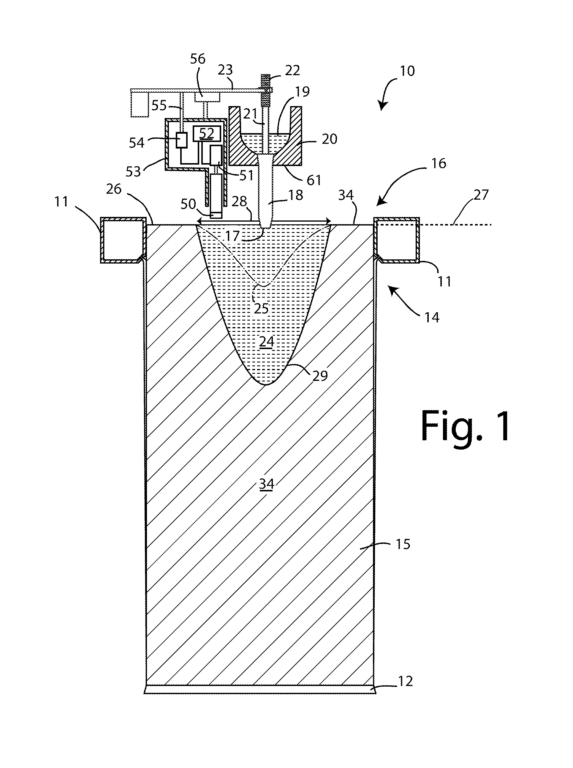
[0102]The procedure of Example 2 is repeated except that an electrical immersion heater is positioned within the trough 20 to provide super-heat for the molten metal before it enters the troughs 18. The heater is operated before casting commences to ensure that freezing of metal does not take place in the spouts 18 as the metal first runs through them. Additionally, the spouts 18 and pins 21 are pre-heated by means of torches, as in Example 2.

[0103]The immersion heater is operated during casting to avoid freezing of metal and is kept in operation when casting is terminated so that, during the topping-up procedure, the molten metal entering the spouts 18 does not freeze. By this means, 12 to 15 topping up iterations are achieved before the spout 18 and pin 21 cool sufficiently to risk blockage.


PUM

PropertyMeasurementUnit
heightaaaaaaaaaa
total heightaaaaaaaaaa

Abstract

An exemplary embodiment provides a method of eliminating a shrinkage cavity in a metal ingot cast by direct chill casting. The method involves casting an upright ingot having an upper surface at an intended height. Upon completion of the casting, the lower tip of the spout is maintained below the molten metal near the center of the upper surface. The metal flow through the spout is terminated and a partial shrinkage cavity is allowed to form as metal of the ingot shrinks and contracts. Before the partial cavity exposes the lower tip of the spout, the cavity is preferably over-filled with molten metal, while avoiding spillage of molten metal, and then the flow of metal through the spout is terminated. These steps are repeated until no further contraction of the metal causes any part of the upper surface to contract below the intended ingot height.

Description

CROSS-REFERENCE TO RELATED APPLICATIONS[0001]This application claims the priority right of prior co-pending U.S. provisional Patent Application Ser. No. 61 / 460,029 filed on Dec. 22, 2010 by applicants named herein. The entire contents of Application Ser. No. 61 / 460,029 are specifically incorporated herein by this reference.BACKGROUND OF THE INVENTION[0002](1) Field of the Invention[0003]This invention relates to the partial or complete elimination of shrinkage cavities in cast ingots. More particularly, the invention relates to the partial or complete elimination of such cavities that form during direct chill (DC) casting of metal ingots, especially (although not exclusively) ingots made of aluminum and aluminum-based alloys.[0004](2) Description of the Related Art[0005]Metal ingots, especially those made of aluminum and aluminum-based alloys, may be formed by direct chill (DC) casting techniques in which molten metal is fed into the upper end of a chilled annular (usually rectangul...

Claims


Application Information

Patent Timeline
Patent Type & Authority Patents(United States)
IPC IPC(8): B22D11/049
CPCB22D11/049B22D11/10B22D11/18B22D41/18B22D11/186B22D11/185B22D19/10B22D7/12B22D15/04
Inventor ANDERSON, MARKBISCHOFF, TODD F.BOORMAN, JAMESFENTON, WAYNE J.SINDEN, DAVIDTINGEY, JOHN STEVENWAGSTAFF, ROBERT BRUCE
Owner NOVELIS INC
Why Eureka
Try Eureka