
Swept source optical coherence tomography (OCT) method and system

a technology of optical coherence tomography and swept source, which is applied in the field of swept source optical coherence tomography (oct) method and system, can solve the problems of reducing the optical power emitted by the source, sweeping the laser at a fast rate, and negative consequences, so as to reduce the requirements of light source sweep speed and increase the imaging range. , the effect of increasing the power

Active Publication Date: 2013-01-01
D4D TECH LP
View PDF2 Cites 20 Cited by
  • Summary
  • Abstract
  • Description
  • Claims
  • Application Information

AI Technical Summary

Benefits of technology

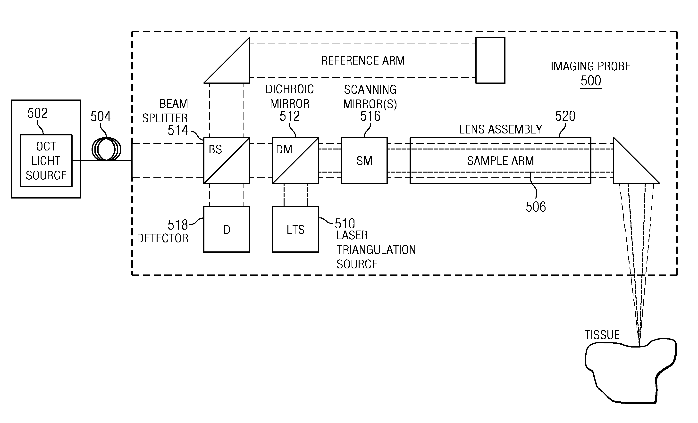
The patent describes a way to do optical coherence tomography (OCT) using a fast scanning mechanism and a slowly swept light source. This method allows for faster position data collection while the light source's wavelength is swept slowly. This reduces the requirements for sweeping the light source, so higher power and greater imaging range can be achieved. Additionally, this method allows for linear sweeps of the source frequency, which improves the quality of the OCT imaging.

Problems solved by technology

Sweeping a laser at a fast rate, however, often comes with negative consequences.
When the sweep rate increases, the light travels less through the gain medium resulting in a decrease in the optical power emitted by the source.
The instantaneous line width of the source can be increased to provide more optical power, but this reduces the useful imaging range of the OCT instrument.

Method used


Image

  • Swept source optical coherence tomography (OCT) method and system
  • Swept source optical coherence tomography (OCT) method and system
  • Swept source optical coherence tomography (OCT) method and system

Examples


Embodiment Construction

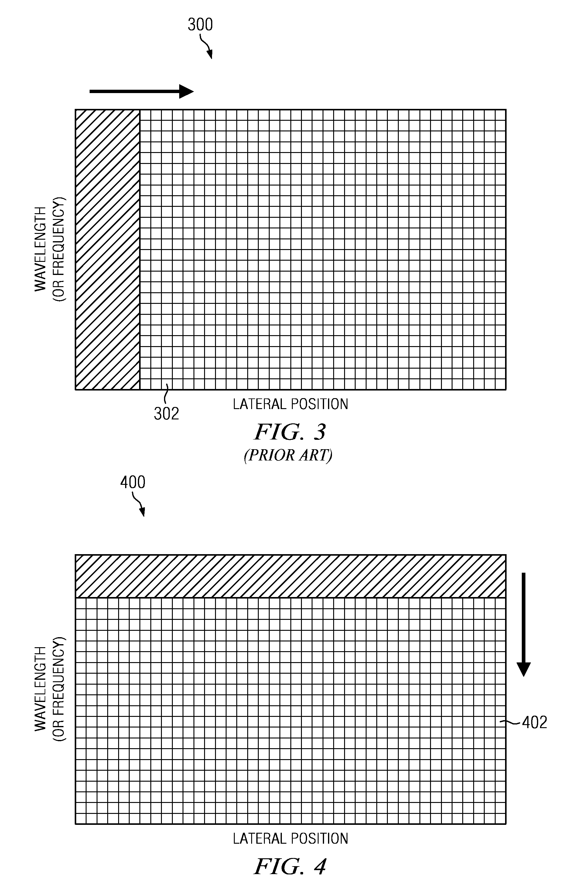
[0021]In this disclosure, in contrast, multiple lateral scans over the same area preferably are performed during a wavelength sweep of the light source. Preferably, the lateral scan is performed with resonant scanning mirrors or polygonal scanning mirrors. In this arrangement, the OCT system becomes limited only by the lateral scan speed of the sample arm rather than the sweep speed of the light source. Preferably, multiple lateral scans are performed over the same region. During each lateral scan, the wavelength of the source remains nearly constant. The wavelength of the source changes for each subsequent lateral scan. For each position along the lateral scan, the interference signal is recorded versus the wavelength or frequency of the swept source.

[0022]In the prior art, a laser sweep rate typically is a product of a frame rate (images / second) and a number of axial scans per image. A sweep rate of this light source herein preferably is the laser scan rate on the specimen divided...


PUM


Abstract

A method and apparatus are provided for a swept source optical coherence tomography (OCT) system utilizing a fast scanning mechanism in the sample arm and a slowly swept light source. The position data is collected rapidly while the wavelength of the source is swept slowly. The system reduces the sweep speed requirements of the light source enabling higher power, greater imaging range, and linear sweeps of the source frequency. The OCT components (or most of them) may be implemented within a hand held imaging probe. In operation, a triangulation scan may be used to orient the imaging probe with respect to a fixed coordinate system; preferably, OCT data captured by the device is then transformed to that same orientation with respect to the fixed coordinate system to improve the scanning results.

Description

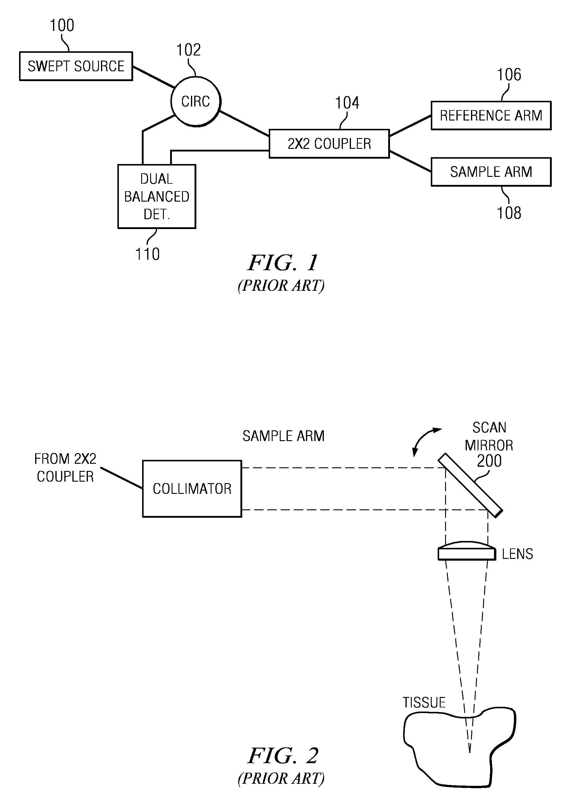
[0001]This application is based on and claims priority from Ser. No. 61 / 170,886, filed Apr. 20, 2009, Ser. No. 61 / 172,513, filed Apr. 24, 2009, and Ser. No. 61 / 173,714, filed Apr. 29, 2009.BACKGROUND[0002]Optical coherence tomography (OCT) is a depth-resolved imaging modality. Reflections of light returning from within the tissue are used to create tomograms of the tissue microstructure.[0003]A known OCT system is described in U.S. Pat. No. 7,355,721. The OCT imaging system described there includes a light source, an optical coupler or beam splitter, a reference arm, a projector, and a sensor. The OCT imaging system also may be coupled to a processor.[0004]An alternative OCT technique uses a swept source. In one known implementation, the wavelength or frequency of a laser is swept over a range supported by the laser's gain medium. This form of OCT is called swept source OCT or optical coherence domain reflectometry (OCDR).[0005]A standard swept source OCT system is illustrated in FI...

Claims


Application Information

Patent Timeline
Patent Type & Authority Patents(United States)
IPC IPC(8): G01B9/02
CPCA61B5/0088G01N21/4795A61C9/0053A61B5/0066A61B5/0062A61B5/0073G01B9/02091G01N2021/1787
Inventor BONNEMA, GARRET T.QUADLING, HENLEY S.QUADLING, MARK S.
Owner D4D TECH LP
Learn More