Solid electrolytic capacitor

a technology of electrolytic capacitors and solids, applied in the direction of fixed capacitor details, fixed capacitors, instruments, etc., can solve the problem that the pad member does not melt easily

Active Publication Date: 2013-01-01
SANYO ELECTRIC CO LTD
View PDF3 Cites 2 Cited by
  • Summary
  • Abstract
  • Description
  • Claims
  • Application Information

AI Technical Summary

Benefits of technology

[0014]In view of above described problems, an object of the present invention is to provide a solid electrolytic capacitor with high assembling precision.
[0016]In the first solid electrolytic capacitor described above, even in a case where the anode section of the capacitor element is arranged at a position spaced apart from the first surface of the insulating substrate, the first anode layer formed on the tip end surface of the pad member can come into contact with the anode section of the capacitor element by adjusting the height dimension of the pad member. Therefore, it is easy to connect electrically the anode section of the capacitor element and the first anode layer to each other, thereby obtaining a good electric connection between the anode section of the capacitor element and the first anode layer.
[0017]Also, in the first solid electrolytic capacitor described above, for the pad member, employed is a material having electrical insulation property. Therefore, even in a case where the anode section of the capacitor element is connected to the first anode layer by welding, the pad member does not melt easily. Accordingly, the height dimension of the pad member is not likely to change, and the pad member is not likely to have positional shift due to pressing force applied to the pad member at the time of welding. Thus, the first solid electrolytic capacitor described above has a high assembling precision.
[0020]According to the third solid electrolytic capacitor described above, the anode section of the capacitor element is fastened by the fitting groove, thereby reducing positional shift of the capacitor element with respect to the insulating substrate. Therefore, the size of the insulating substrate can be smaller by the amount of reduction of the positional shift, resulting in improvement of a space factor of the capacitor element. Also, since a part of the first anode layer is formed on the inner surface of the fitting groove, a good electric connection between the first anode layer and the anode section of the capacitor element is obtained.
[0022]According to the fourth solid electrolytic capacitor described above, although stress is applied to the pad member when the anode section of the capacitor element fits each fitting groove, the stress is relaxed by the slit formed in the pad member. Therefore, damage of the pad member is prevented.

Problems solved by technology

Therefore, even in a case where the anode section of the capacitor element is connected to the first anode layer by welding, the pad member does not melt easily.

Method used


Image

  • Solid electrolytic capacitor
  • Solid electrolytic capacitor
  • Solid electrolytic capacitor

Examples


Embodiment Construction

[0044]A preferred embodiment of the present invention is described in detail below with reference to the drawings.

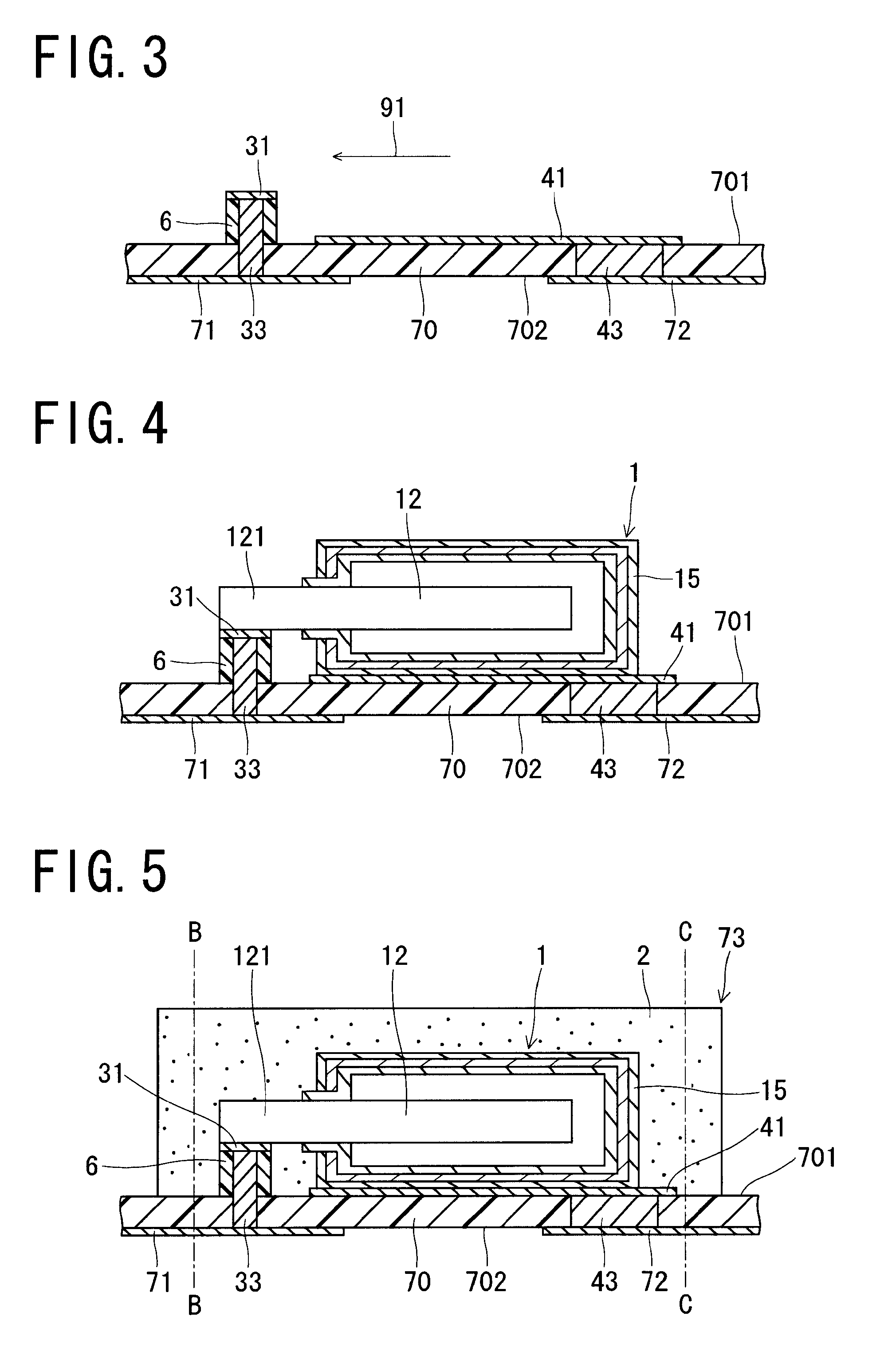
[0045]FIG. 1 is a cross sectional view showing a solid electrolytic capacitor in accordance with an embodiment of the present invention. As shown in FIG. 1, the solid electrolytic capacitor of this embodiment includes an insulating substrate 5, and a capacitor element 1 which is lead type and electrolyte type. The capacitor element 1 is mounted on the insulating substrate 5, and is buried in an enclosure resin 2.

[0046]The insulating substrate 5 includes a first surface 51, on which a first cathode layer 41 is formed, and the capacitor element 1 is mounted on the first cathode layer 41.

[0047]Also, on the first surface 51 of the insulating substrate 5, a pad member 6 projects at a position spaced apart from the first cathode layer 41 in a predetermined direction (a first direction 91). The pad member 6 has electrical insulation property, and includes a tip end surface on w...


PUM


Abstract

The solid electrolytic capacitor includes a solid electrolyte type capacitor element including a dielectric layer intervening between an anode section and a cathode section, and an insulating substrate. The insulating substrate includes a first surface on which the capacitor element is mounted and a second surface opposite to the first surface. The first surface is provided thereon with a first anode layer to which the anode section is electrically connected and a first cathode layer to which the cathode section is electrically connected. The second surface is provided thereon with a second anode layer electrically connected to the first anode layer and a second cathode layer electrically connected to the first cathode layer. Here, a pad member with electrical insulation property projects on the first surface of the insulating substrate, and the first anode layer is formed on a tip end surface of the pad member.

Description

[0001]The Japanese patent application Number 2009-194283, upon which this patent application is based, is hereby incorporated by reference.BACKGROUND OF THE INVENTION[0002]1. Field of the Invention[0003]The present invention relates to a solid electrolytic capacitor in which a solid electrolyte type capacitor element is mounted on an insulating substrate.[0004]2. Description of Related Art[0005]FIG. 16 is a cross sectional view of a conventional solid electrolytic capacitor. As shown in FIG. 16, the conventional solid electrolytic capacitor has a solid electrolyte type capacitor element 100, an anode terminal 130, and a cathode terminal 140, which are buried in an enclosure resin 120. The capacitor element 100 has a dielectric layer 103 formed on a surface of an anode body 101 in which an anode lead 102 is planted, an electrolyte layer 104 formed on the dielectric layer 103, and a cathode layer 105 formed on the electrolyte layer 104.[0006]The anode terminal 130 includes one end par...

Claims


Application Information

Patent Timeline
Patent Type & Authority Patents(United States)
IPC IPC(8): G01R31/12H01G9/00
CPCH01G9/012H01G9/15
Inventor MATSUOKA, KEIKO
Owner SANYO ELECTRIC CO LTD
Why Eureka
Try Eureka