
Pressure sensor, and its manufacturing method

a technology of pressure sensor and manufacturing method, which is applied in the direction of fluid pressure measurement using elastically deformable gauges, fluid pressure measurement using capacitance variation, instruments, etc., can solve the problems of high difficult to reduce size, and difficult to retain high assembling precision, so as to achieve the effect of small dispersion of operating characteristics

Inactive Publication Date: 2005-07-12
ORMON CORP
View PDF1 Cites 2 Cited by
  • Summary
  • Abstract
  • Description
  • Claims
  • Application Information

AI Technical Summary

Benefits of technology

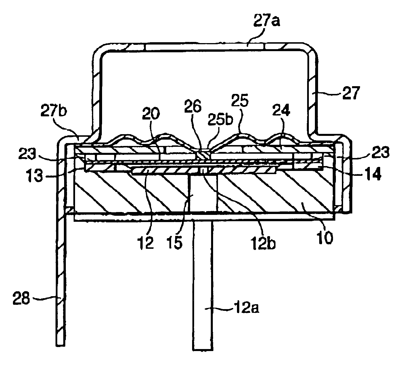
[0008]In view of the aforementioned problem, the present invention has an object to provide a small-sized pressure sensor having smaller numbers of parts and assembling steps, a simple structure, a high assembly precision, and little dispersion in the operating characteristics, and a method for manufacturing the pressure sensor.
[0010]According to an aspect of the invention, therefore, the upper face of the stationary electrode molded integrally with the base member and the upper faces of the moving electrode receiving portions are arranged to have the predetermined inter-electrode gap. Therefore, the outer circumferential edge portion of the moving electrode is mounted on and assembled integrally with the moving electrode receiving portions. It is, therefore, possible to provide the small-sized pressure sensor, which not only has the small numbers of parts and assembling steps and the simple structure but also can assemble the moving electrode in the high assembly precision on the base member so that it has the little dispersion in the operating characteristics.
[0012]According to this embodiment, therefore, the shield cover removes electrostatic disturbances or the like so that it provides a highly reliable pressure sensor. Moreover, the diaphragm is protected by the shield cover because it is less attacked by scattered objects. By handling the shield cover manually, still moreover, the thin and fragile diaphragm need not be touched to enhance the workability.
[0014]According to this embodiment, the outer circumferential edge portion of the diaphragm is welded integrally with the outer circumferential edge portion of the disc while being clamped between the outer circumferential edge portion of the disc and the step portion of the shield cover. Therefore, the thermal shrinkage after the welding operation is suppressed to reduce the thermal stress to the diaphragm thereby to reduce the dispersion of the operating characteristics.
[0016]According to this embodiment, the bent ribs of the diaphragm are clamped between the shield portion of the shield cover and the ribs of the fitting portion and are integrally welded. Therefore, the thermal stress exerts, it any generated by the welding operation, little adverse influence directly to the diaphragm body, thereby to provide the pressure sensor having less dispersion in the operating characteristics.

Problems solved by technology

However, the pressure sensor of the prior art has a large number of parts and a complicated structure so that it has a large number of assembling steps and is difficult to reduce the size.
Moreover, an accumulated error is so high as to make it difficult to retain a high assembling precision.
This raises a problem that the dispersion of the operating characteristics is high.

Method used


Image

  • Pressure sensor, and its manufacturing method
  • Pressure sensor, and its manufacturing method
  • Pressure sensor, and its manufacturing method

Examples


Embodiment Construction

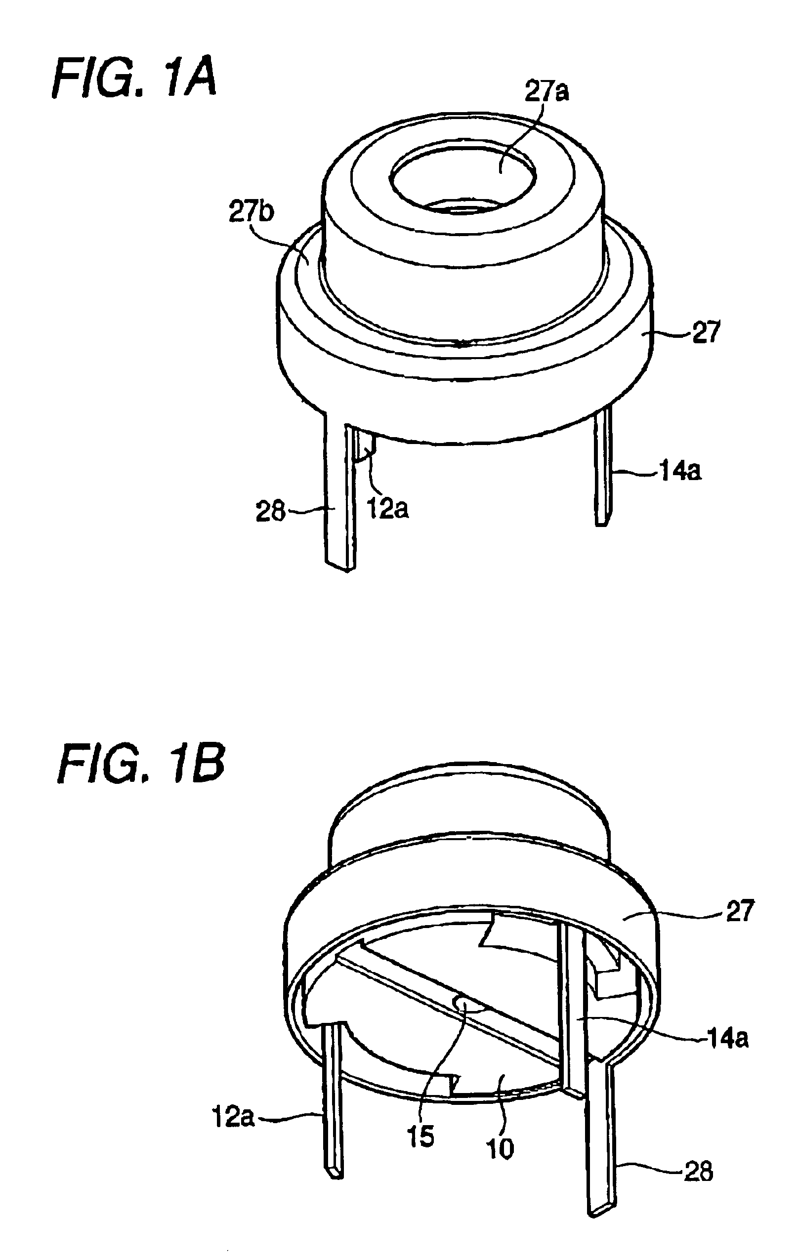
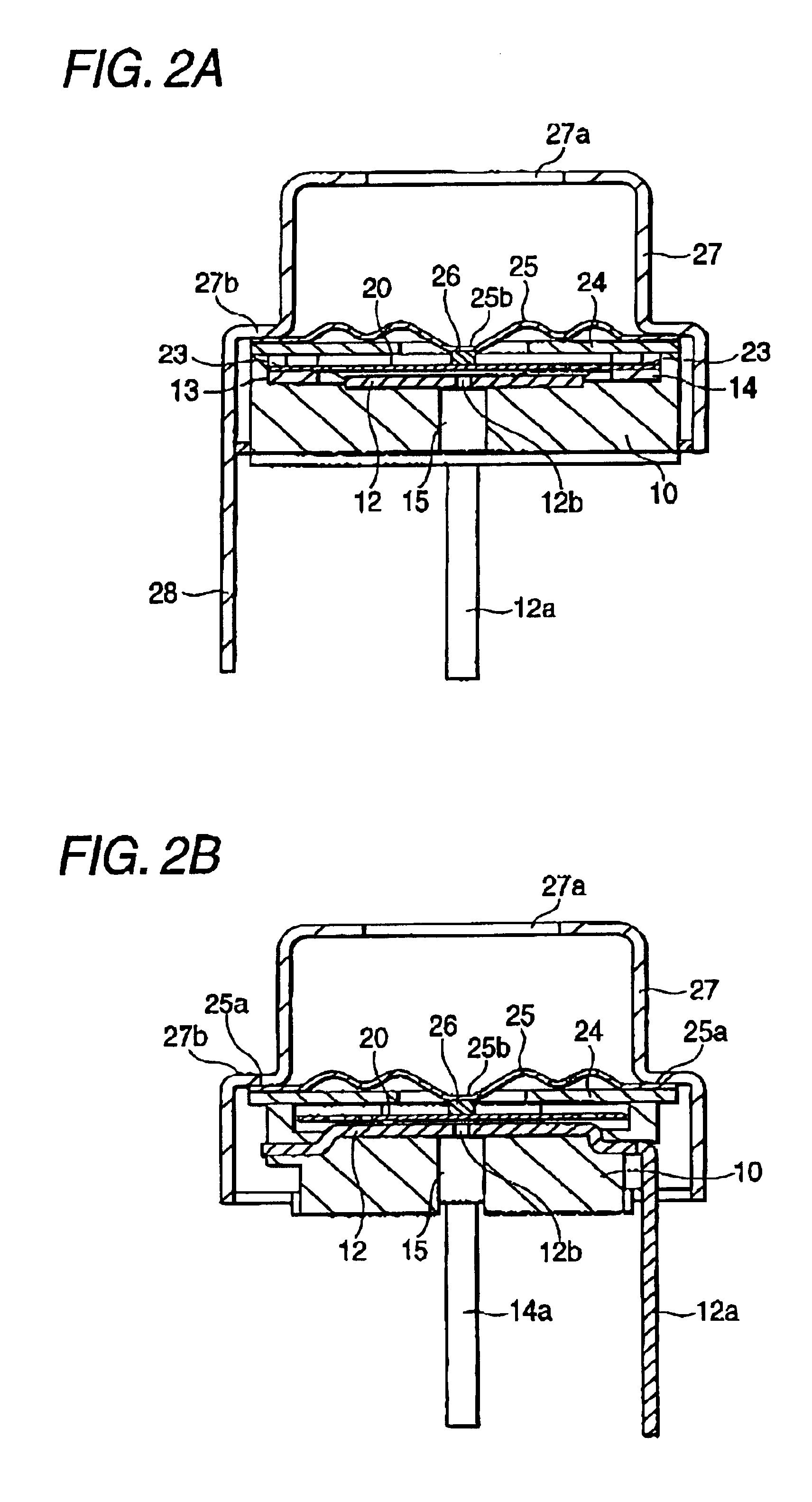
[0032]An embodiment of the pressure sensor according to the invention will be described with reference to FIG. 1 to FIG. 12.

[0033]In the first embodiment, as shown in FIG. 1 to FIG. 9, a moving electrode 20, a disc 24 and a diaphragm 25 are assembled with a base member 10, and a shield cover 27 is integrally fitted on the base member 10.

[0034]The base member 10 is insert-molded not only with a disc-shaped stationary electrode 12 into the bottom center of its recess 11 but also with moving electrode receiving portions 13 and 14, as will be described hereinafter, at positions opposed across the stationary electrode 12. Between the upper face of the stationary electrode 12 and the upper faces of the receiving portions 13 and 14, there are formed steps for inter-electrode gaps, as apparent from FIGS. 4B and 4C. Moreover, the stationary electrode 12 is provided with an air hole 12b at its center and has a terminal 12a extending therefrom. On the other hand, the moving electrode receiving...


PUM

PropertyMeasurementUnit
heightaaaaaaaaaa
diameteraaaaaaaaaa
circumferenceaaaaaaaaaa

Abstract

A small-sized pressure sensor having smaller numbers of parts and assembling steps, a simple structure, a high assembly precision, and little dispersion in the operation characteristics, and a method for manufacturing the pressure sensor. The pressure sensor comprises: a base member; a stationary electrode molded so integrally as is exposed from the bottom face of a recess formed in the upper face of the base member; moving electrode receiving portions and molded so integrally in the bottom face of the recess of the base members as are arranged in the periphery of the stationary electrode and as are higher by a predetermined inter-electrode gap than the upper face of the stationary electrode; a moving electrode opposed to the upper face of the stationary electrode through a predetermined inter-electrode gap; and a diaphragm fixed of the open edge portion of the recess of the base member and adhered integrally at the central portion of its lower face to the upper face of the moving electrode.

Description

BACKGROUND OF THE INVENTION[0001]1. Field of the Invention[0002]The present invention relates to a pressure sensor and, more particularly, to an electrostatic capacity type pressure sensor to be packaged in an industrial device.[0003]2. Description of the Related Art[0004]As the electrostatic capacity type pressure sensor to be packaged in the industrial device of the prior art, there is a pressure sensor (as referred to Patent Publication 1), which comprises: a pressure receiving unit having a pressure receiving portion for sensing the pressure of a pressure fluid; a sensor unit having a sensor portion including stationary electrodes, and a moving electrode made movable in response to the pressure sensed by the pressure receiving unit and insulated and held between the stationary electrodes; and a signal processing unit having a reference portion and processing the electrostatic capacities of the sensor portion and the reference portion for outputting a desired signal.[0005][Patent...

Claims


Application Information

Patent Timeline
Patent Type & Authority Patents(United States)
IPC IPC(8): G01L7/00G01L9/12G01L9/00
CPCG01L9/0072
Inventor SHIMOMOTO, YASUSHISHINOHARA, KENJIKISHIMOTO, OSAMUIZAWA, KAZUHIRA
Owner ORMON CORP
Learn More