Infrared suppression system with spiral septum

a technology of infrared suppression and spiral septum, which is applied in the direction of efficient propulsion technology, machines/engines, transportation and packaging, etc., can solve the problems of reducing the velocity of exhaust flow, re-ingesting into the engine, and limited conventional ir suppressor systems, so as to minimize the aerodynamic impact of aircraft, minimize the impact of exhaust impingement, and effectively hide and cool the exhaust components

Inactive Publication Date: 2013-01-01
SIKORSKY AIRCRAFT CORP
View PDF8 Cites 5 Cited by
  • Summary
  • Abstract
  • Description
  • Claims
  • Application Information

AI Technical Summary

Benefits of technology

[0011]The InfraRed Suppression System (IRSS) according to the present invention generally includes a double-walled exhaust duct and double walled spiral septum therein. The double walled structure provides a flow path for secondary (non-exhaust gas) cooling airflow to spiral septum slots in surfaces exposed to the exhaust gases. Exhaust gas which flows past these slots draws cooling air across the exhaust duct and spiral septum surfaces. This cooling flow cools the surfaces and mixes with exhaust gasses downstream to cool the exhaust plume.
[0013]The exhaust duct may also be shrouded by a fairing which provides contour which minimizes aerodynamic impact on the aircraft. Since elevated fairing temperatures contributes to the total aircraft IR signature, the fairing design and surrounding structure further provides convective cooling and minimizes exhaust impingement onto surfaces viewable by anticipated threats.
[0014]The IRSS design effectively hides and cools heated exhaust components, the IRSS achieves a significant reduction to the entire aircraft IR signature. The exhaust duct and spiral septum arrangement IRSS minimizes exhaust flow restrictions thus minimizing power loss of the associated engine.
[0015]The present invention therefore provides an Infrared Suppression System which reduces the overall IR signature of the aircraft, is compact in design, masks the IR energy emitted / radiated from a gas turbine engine for a given viewing / azimuth angle, and minimizes impingement of engine exhaust onto adjacent aircraft structure while maintaining engine performance and residual thrust.

Problems solved by technology

With respect to the former, a heat-seeking missile may obtain directional cues from infrared energy generated by the engine exhaust such that the amount of infrared energy is one of the primary determining factors of a missile's accuracy, and consequently, lethality.
Such conventional IR suppressor systems are limited by packaging space restrictions thereof in which a relatively significant area is required to provide ample mixing and flow area.
Disadvantageously, the mixing operation reduces the velocity of the exhaust flow such that the exhaust velocity may be too low to expel the exhaust far enough from the fuselage to avoid such a “hot spot.” A farther disadvantage is that if the exhaust may not have enough velocity to escape rotor downwash and the exhaust gas may be re-ingested into the engines which reduces engine efficiency.

Method used


Image

  • Infrared suppression system with spiral septum
  • Infrared suppression system with spiral septum
  • Infrared suppression system with spiral septum

Examples


Embodiment Construction

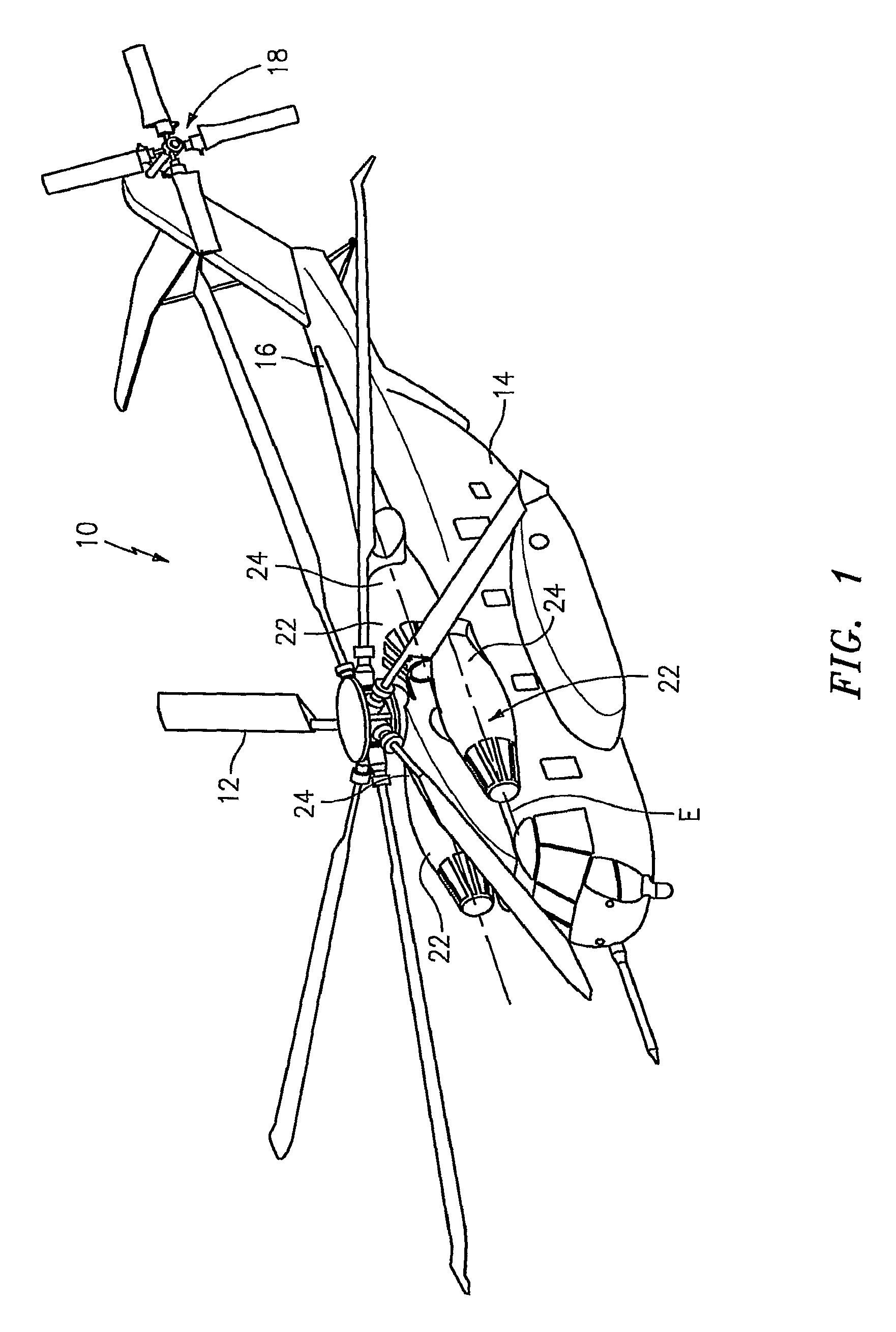
[0025]FIG. 1 schematically illustrates a rotary-wing aircraft 10 having a main rotor system 12. The aircraft 10 includes an airframe 14 having an extending tail 16 which mounts an anti-torque tail rotor system 18. The main rotor system 12 is driven about an axis of rotation A through a transmission (illustrated schematically at 20) by one or more gas turbine engines 22. Although a particular helicopter configuration is illustrated in the disclosed embodiment, other configurations and / or machines will also benefit from the present invention.

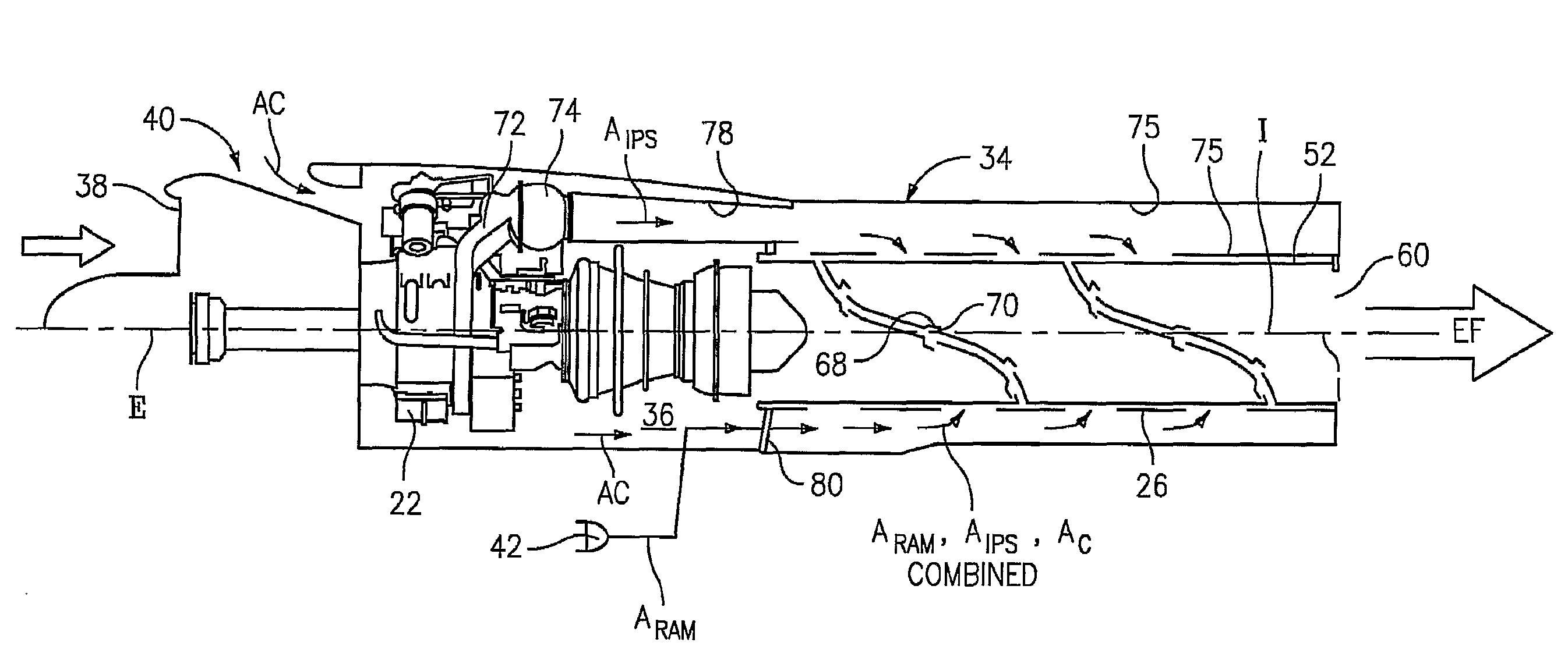
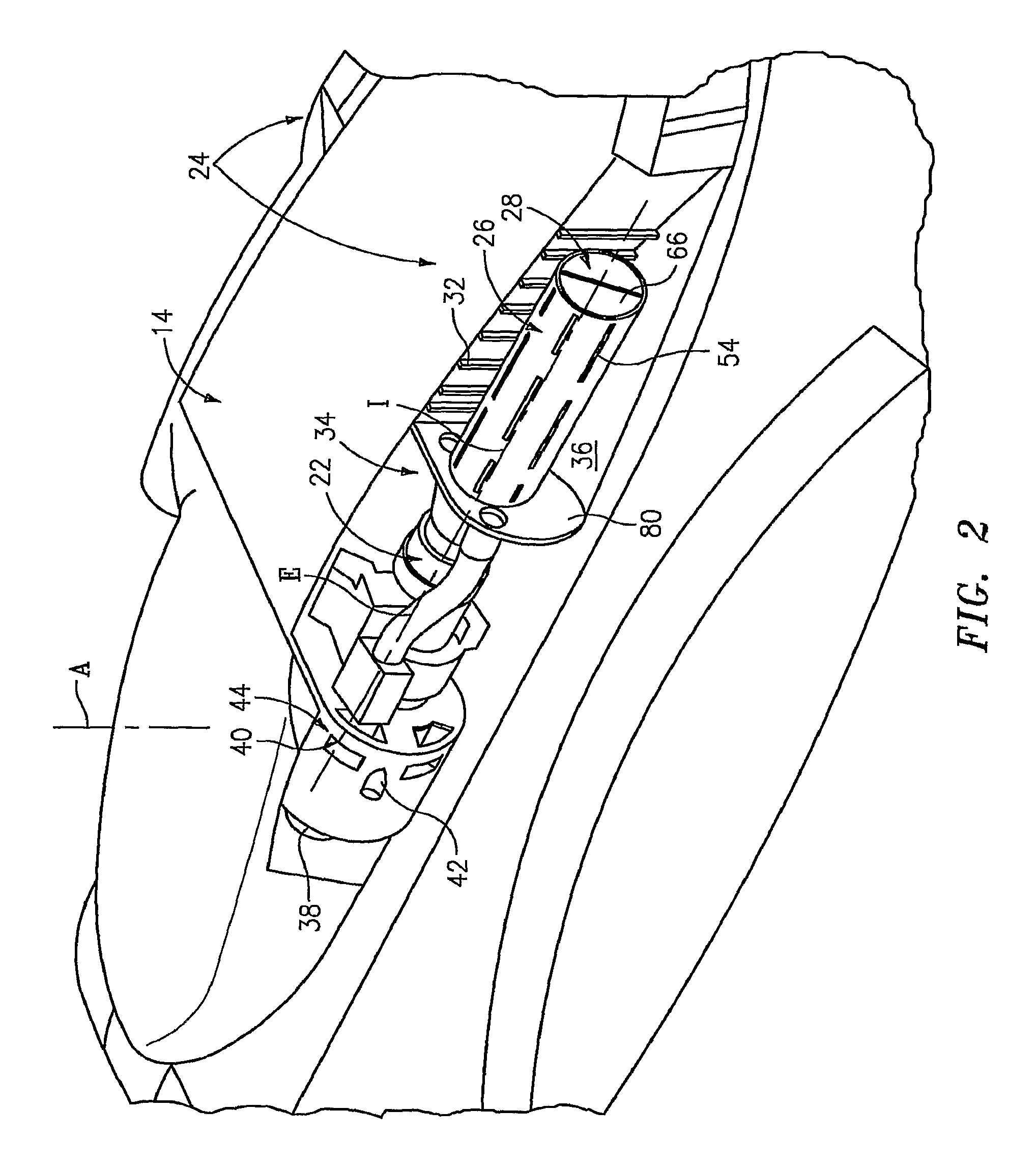
[0026]The rotary wing aircraft 10 also includes an InfraRed Suppression System (IRSS) 24 in communication with each gas turbine engine 22. The IRSS 24 suppresses the IR signature radiating from the high-temperature exhaust generated by the gas turbine engines 22. In the context used herein, “suppress” means that the TR signature emanating from the gas turbine engine 22 is reduced below that expelled by the gas turbine engine 22 after passage throu...


PUM


Abstract

An InfraRed Suppression System (IRSS) includes a double-walled exhaust duct and double walled septum. The double walled structure provides a flow path for secondary (non-exhaust gas) cooling air flow to slots along the surfaces exposed to exhaust gases. Exhaust gas flow past these slots draws cooling air across the duct and septum surfaces. This flow cools the surfaces close to the slots and mixes with exhaust gasses downstream to cool the exhaust plume. The septum in the shape of a helix rotating 360° fully blocks line-of-sight to the turbine exit from the aft of the aircraft. The exhaust duct is intended to be shrouded by an aerodynamic fairing which provides an aerodynamic contour which minimizes aerodynamic impact on the aircraft.

Description

[0001]The present application claims priority to U.S. Provisional Patent Application Ser. No. 60 / 777,658, filed Feb. 27, 2006.BACKGROUND OF THE INVENTION[0002]The present invention relates to an infrared suppression system (IRSS), and more particularly to an infrared suppression system which uses a film-cooled spiral septum within an exhaust duct to mask the engine exhaust and reduce the overall infrared signature of an aircraft.[0003]The exhaust plume and plume-heated surfaces from a gas turbine engine may be a source of infrared (IR) energy which may be detected by heat seeking missiles and / or various forms of infrared imaging systems for targeting / tracking purposes. With respect to the former, a heat-seeking missile may obtain directional cues from infrared energy generated by the engine exhaust such that the amount of infrared energy is one of the primary determining factors of a missile's accuracy, and consequently, lethality. Regarding the latter, infrared imaging systems dete...

Claims


Application Information

Patent Timeline
Patent Type & Authority Patents(United States)
IPC IPC(8): F02K1/38
CPCF02K1/825Y02T50/671Y02T50/60
Inventor CHAPKOVICH, III, JOHN S.VOEGELI, HENRY E.BLAIR, NATHAN C.MATH, JEFFREY A.
Owner SIKORSKY AIRCRAFT CORP
Why Eureka
Try Eureka