
Methods and apparatus for waveform based variational static timing analysis

a static timing analysis and waveform technology, applied in the field of static timing analysis of integrated circuits, can solve the problems of change in performance and yield, variation has become significant and cannot be ignored, and conventional static timing analysis tools are often inability to capture non-idealities in waveforms

Inactive Publication Date: 2012-12-25
CADENCE DESIGN SYST INC
View PDF21 Cites 15 Cited by
  • Summary
  • Abstract
  • Description
  • Claims
  • Application Information

AI Technical Summary

Benefits of technology

The invention is a system and method for analyzing the timing of signals in electronic circuits. It uses a combination of linear and non-linear modeling techniques to create a representation of the circuit's behavior based on the input waveform. This representation is then used to perform static timing analysis, which helps to determine the timing of output signals. The invention can be useful in designing and testing new circuits, improving their performance, and ensuring they function correctly.

Problems solved by technology

Timing and signal integrity are ever increasingly important issues in integrated circuit design, particularly due to drastic scaling down rate of layout geometries as well as the increase in operating frequency.
Variations in semiconductor processing of an integrated circuit can cause changes in its performance and yield.
In nanometer technologies, the variations have become significant and can not be ignored.
Conventional static timing analysis tool are often unable to capture non-idealities in the waveforms, for example, overshoots, spikes, ringing, etc.
Additionally, it is often difficult to exhaustively characterize the cells for all possible loading conditions.
Due to these approximations and the intrinsic limitations of the models, the generated output waveforms do not match the real circuit behavior.
The problem is more severe in the case of non-linear loading conditions, such as when other gates are coupled to the output of the driver as fan-out gates.
The problem is further exacerbated due to large changes in transistor and interconnects characteristics in the presence of process variations.

Method used


Image

  • Methods and apparatus for waveform based variational static timing analysis
  • Methods and apparatus for waveform based variational static timing analysis
  • Methods and apparatus for waveform based variational static timing analysis

Examples


Embodiment Construction

[0033]In the following detailed description of the embodiments of the invention, numerous specific details are set forth in order to provide a thorough understanding of the embodiments of the invention. However, the embodiments of the invention may be practiced without these specific details. In other instances well known methods, procedures, components, and circuits have not been described in detail so as not to unnecessarily obscure aspects of the embodiments of the invention.

Introduction

[0034]In general, static timing analysis (STA) involves identifying timing paths within the design, calculating delay of each path, and finally comparing the path delay against timing constraints specified in the design. The basic idea of STA is based on representation of logic function by Boolean variables (variables that can take on values of logical zero and one). In traditional STA methodologies, logic levels and corresponding valid transitions between them are propagated from one stage (gate)...


PUM


Abstract

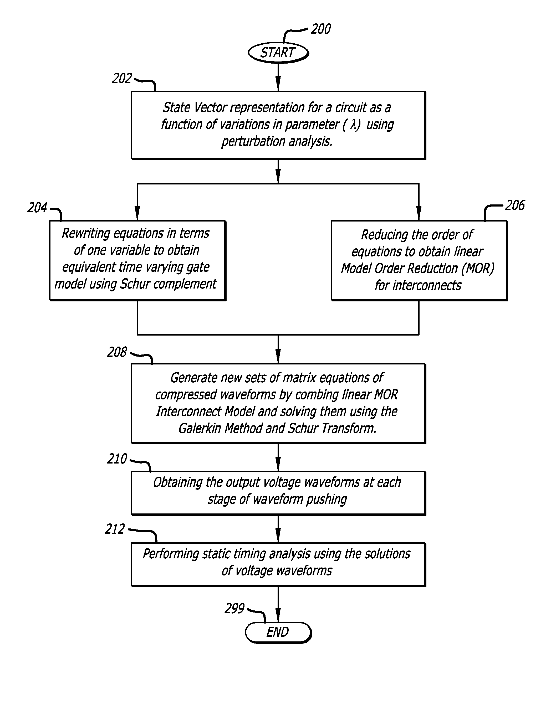
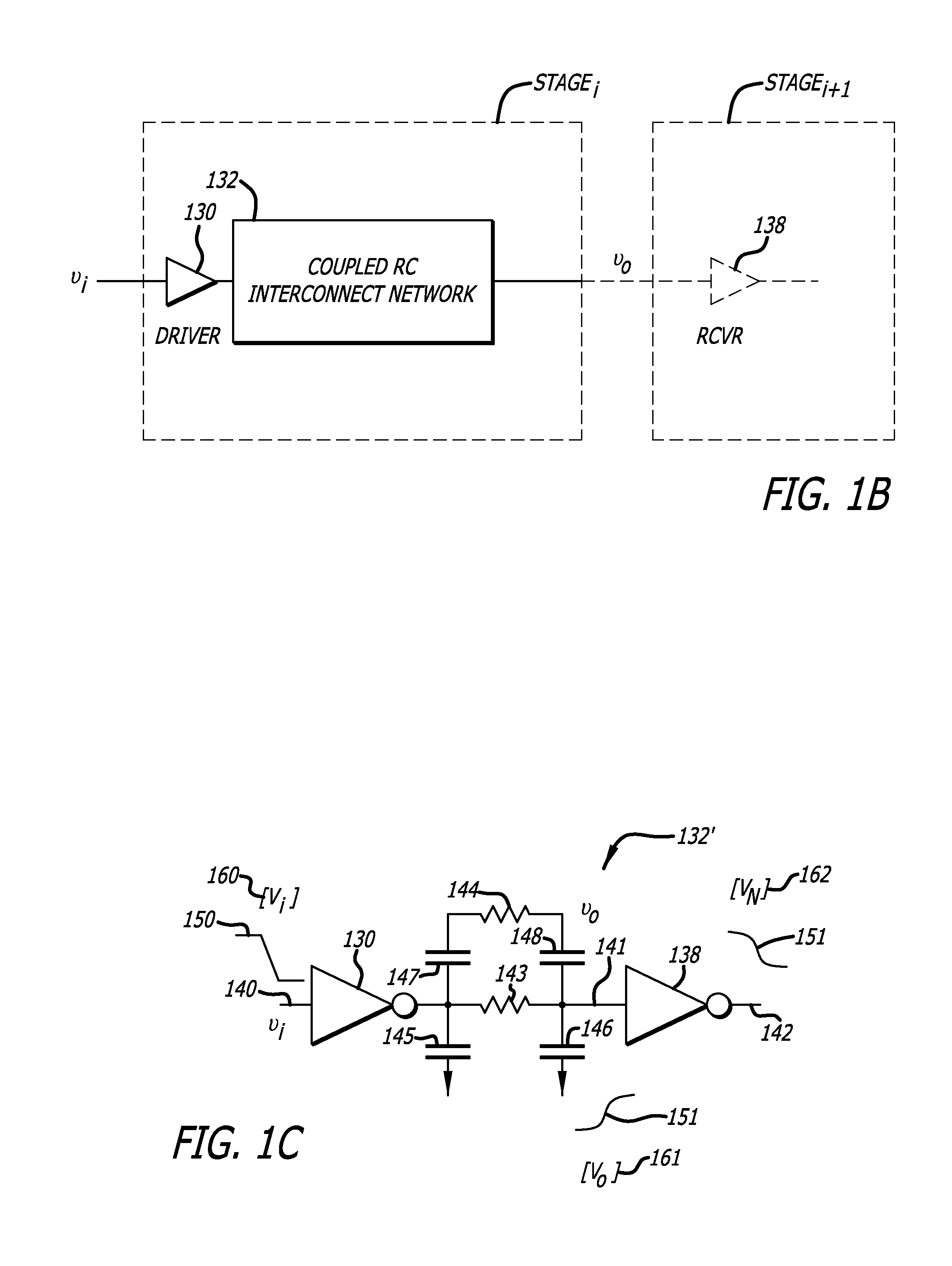
A system and method are disclosed for waveform based variational static timing analysis. A circuit is divided into its linear circuit parts and non-linear circuit parts and modeled together, by a combination of linear modeling techniques, into linear equations that may be represented by matrices. The linear equations in matrix form may be readily solved by a computer such that an input waveform to an input pin of the circuit can be sequentially “pushed” through the various interconnects and logic networks of the circuit to an output pin. Output voltage waveforms are obtained at each stage of the waveform pushing and may be used to perform static timing analysis.

Description

CROSS REFERENCE TO RELATED APPLICATIONS[0001]This non-provisional United States (U.S.) patent application claims the benefit of provisional U.S. Patent Application No. 61 / 044,464 filed on Apr. 11, 2008 by inventors Saurabh Tiwary et al., entitled WAVEFORM BASED VARIATIONAL STATIC TIMING ANALYSIS, and is incorporated herein in its entirety by reference.FIELD[0002]The embodiments of the invention generally relate to static timing analysis of integrated circuits with consideration of semiconductor process and environmental variations.BACKGROUND[0003]Electronic Design Automation (EDA) is used extensively in the design of integrated circuits. An electronic circuit under design is evaluated using models of devices and interconnections between the devices. A simulation using these models is then run to test the performance of the circuit.[0004]Timing and signal integrity are ever increasingly important issues in integrated circuit design, particularly due to drastic scaling down rate of la...

Claims


Application Information

Patent Timeline
Patent Type & Authority Patents(United States)
IPC IPC(8): G06F9/455G06F17/50
CPCG06F17/5031G06F30/3312
Inventor TIWARY, SAURABH K.PHILLIPS, JOEL R.KELLER, IGOR
Owner CADENCE DESIGN SYST INC
Learn More